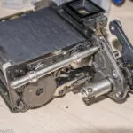
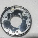
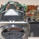
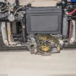
About a year ago, I bought a Minolta XG-M 35 mm film camera kit from an auction on eBay. The kit consisted of the camera itself, the Minolta 50 mm f/1.7 standard lens which was supplied with the camera when new, a Vivitar 28-85 mm zoom and I think there was also a cheap Vivitar electronic flash in the case as well.
Since I paid only about £10 for the complete kit, I was happy just to receive the 50 mm standard lens; all the other kit such as the Minolta XG-M body and zoom lens was a bonus, so I wasn't too upset when I found the camera didn't work. It's been on the back of my mind for a while to try to fix it, however, so a couple of weeks ago I picked it up and had a look at what was wrong with it.
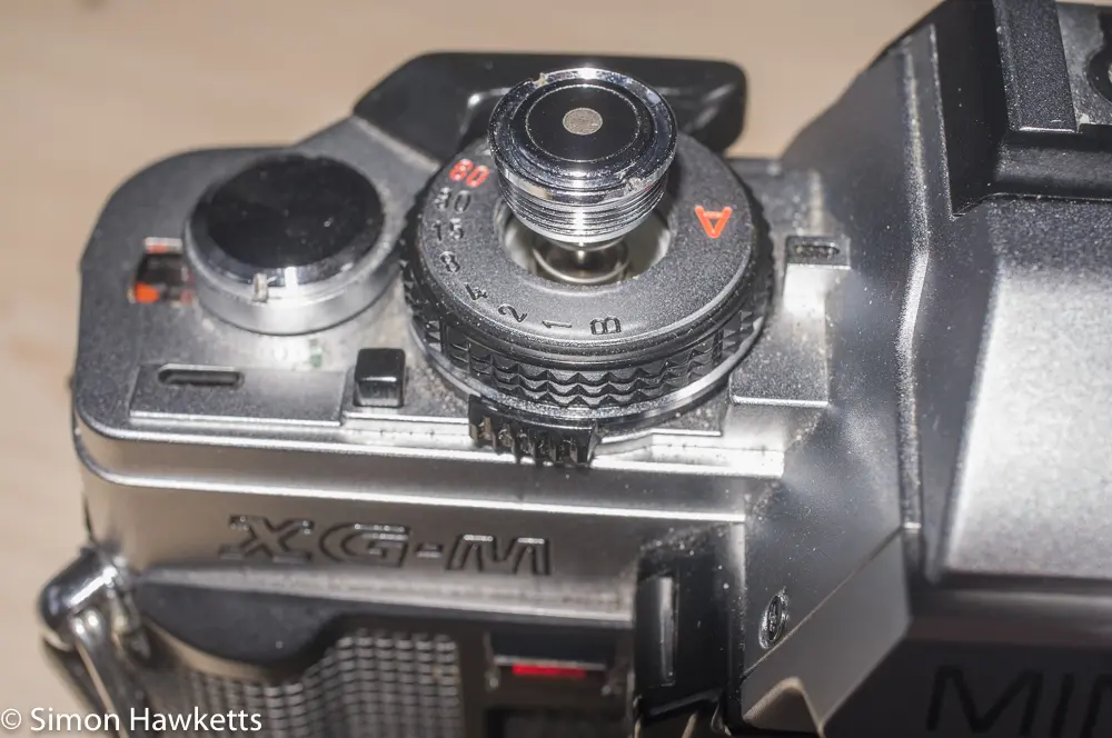
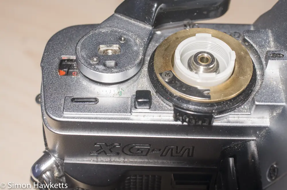
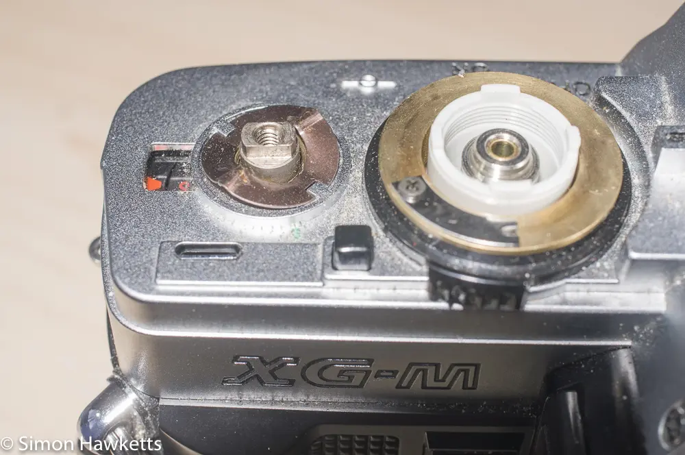
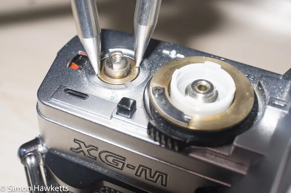
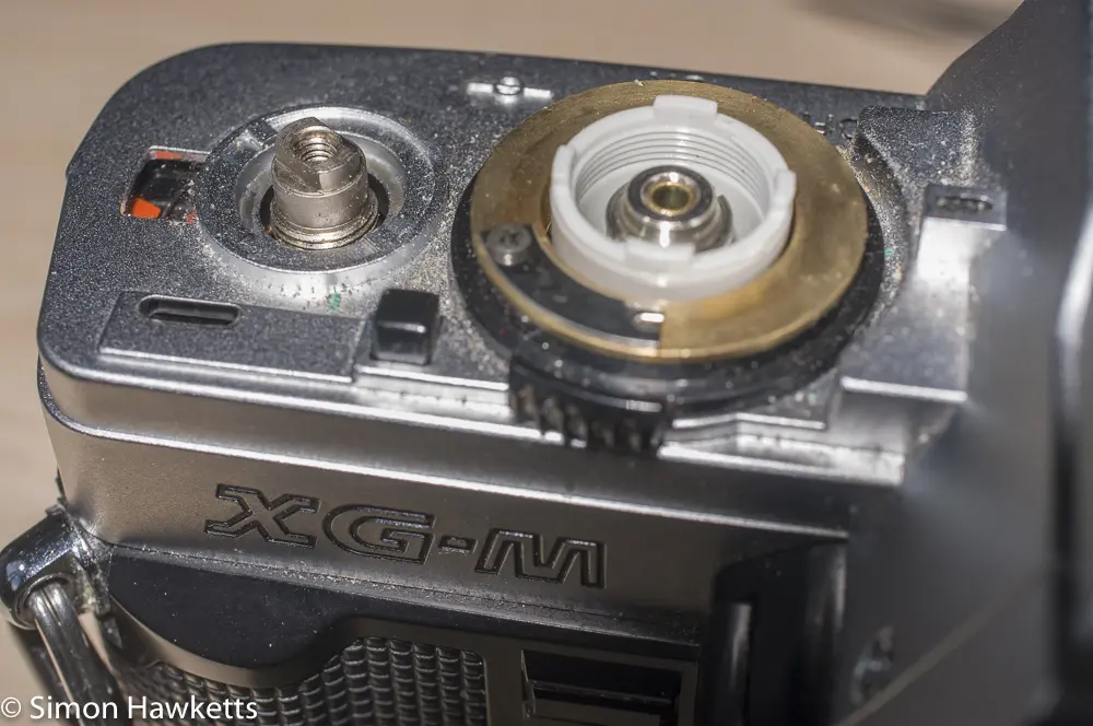
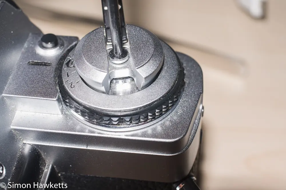
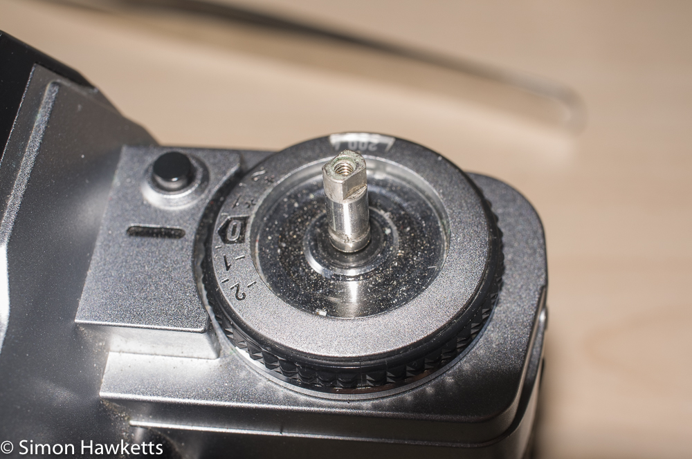
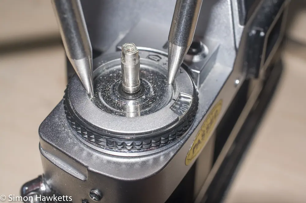
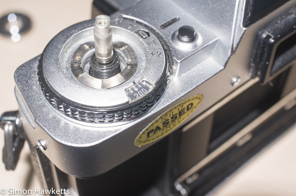
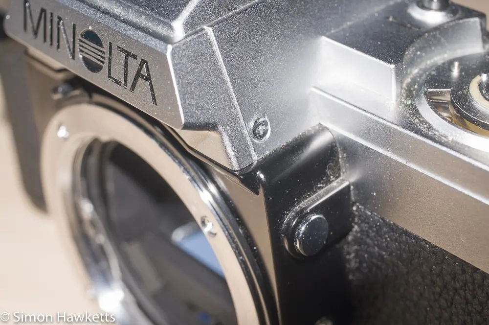
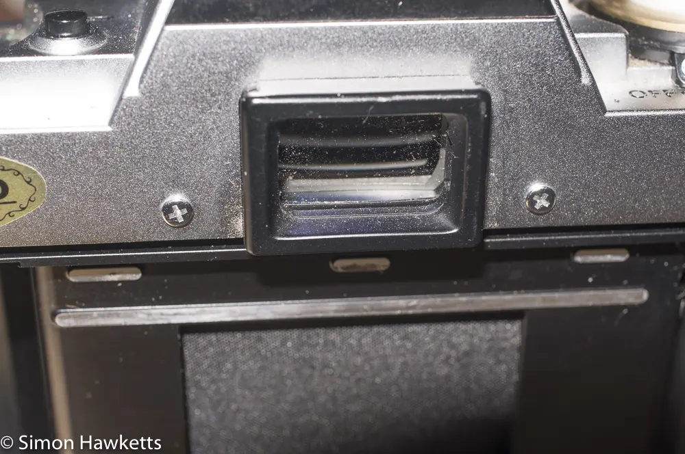
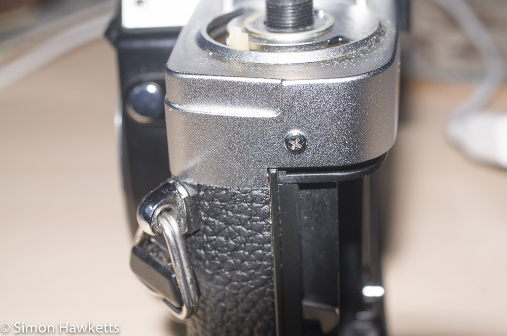
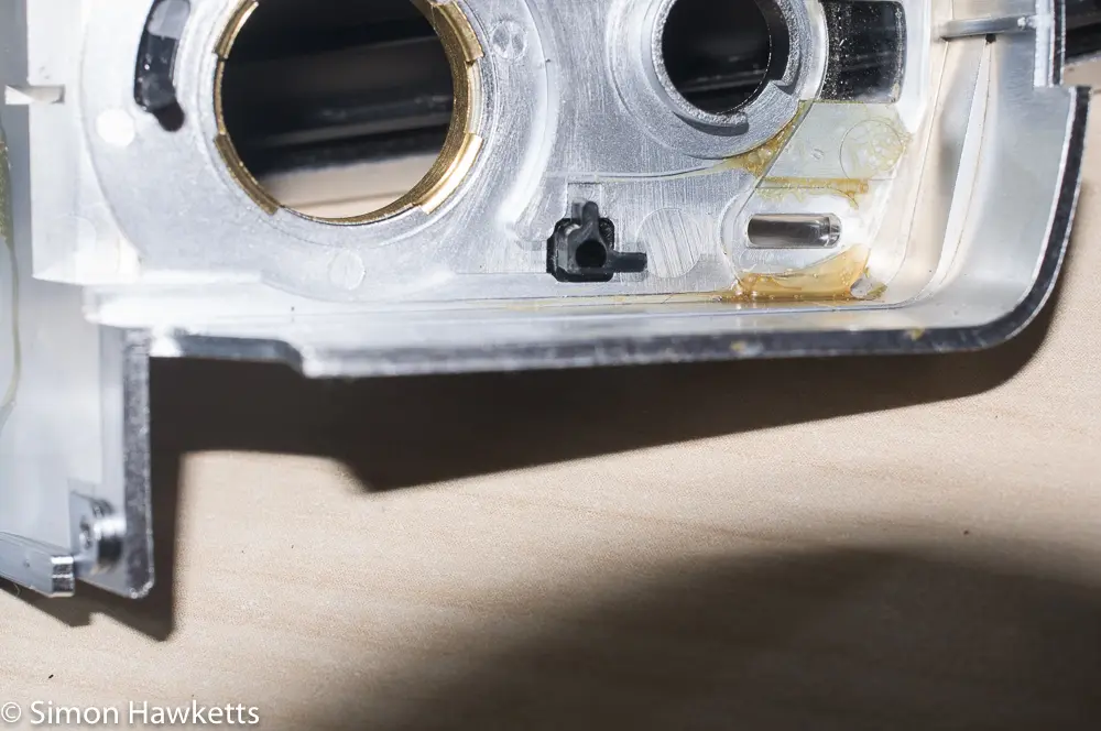
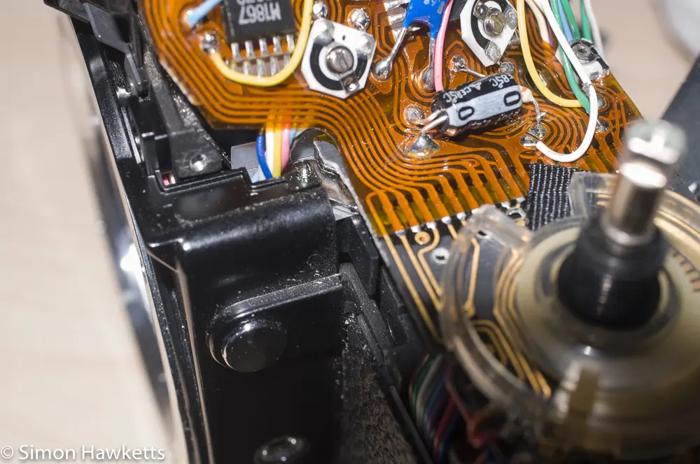
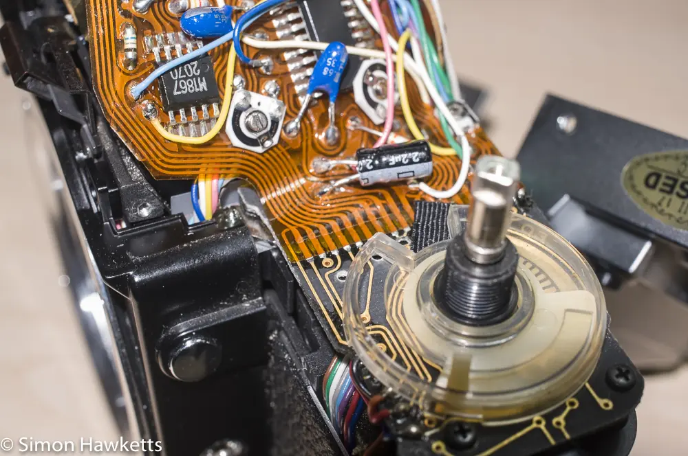
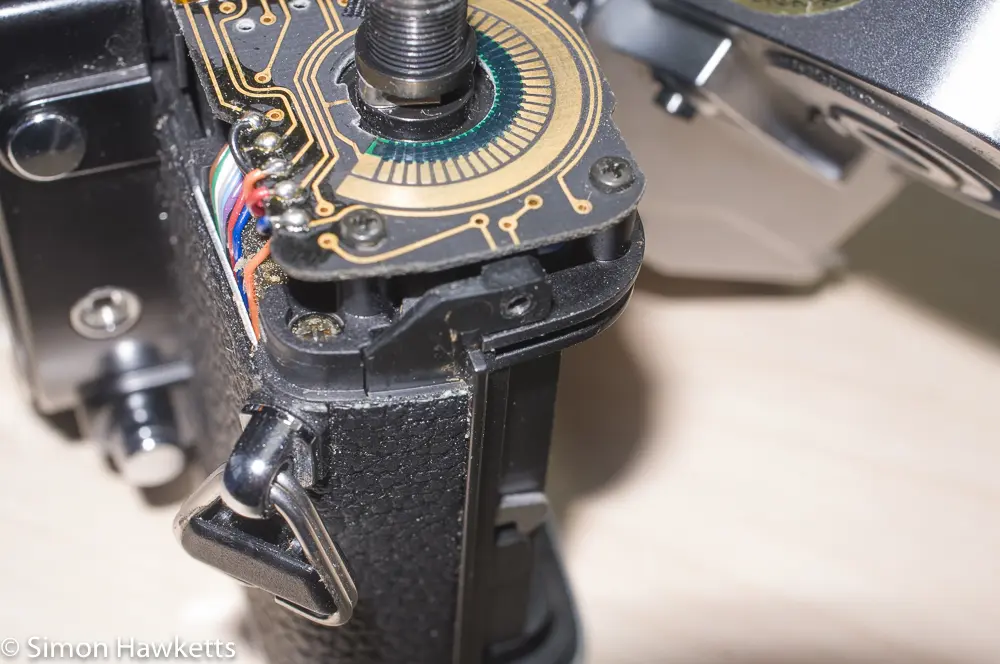
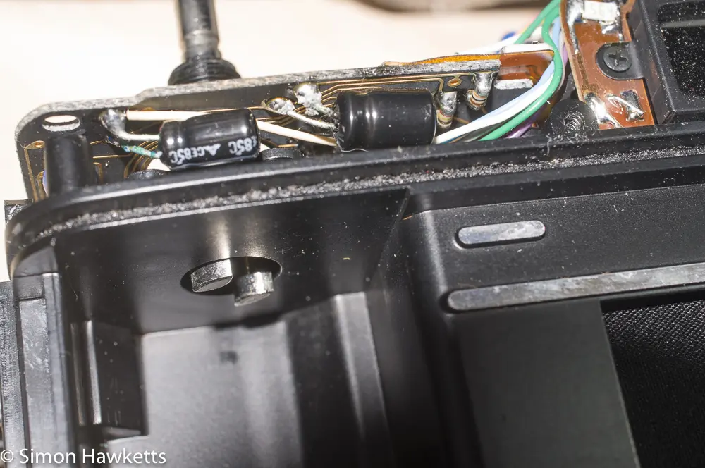
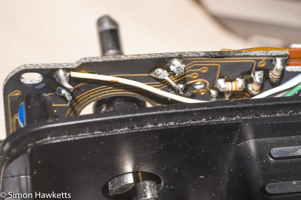
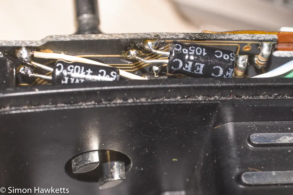
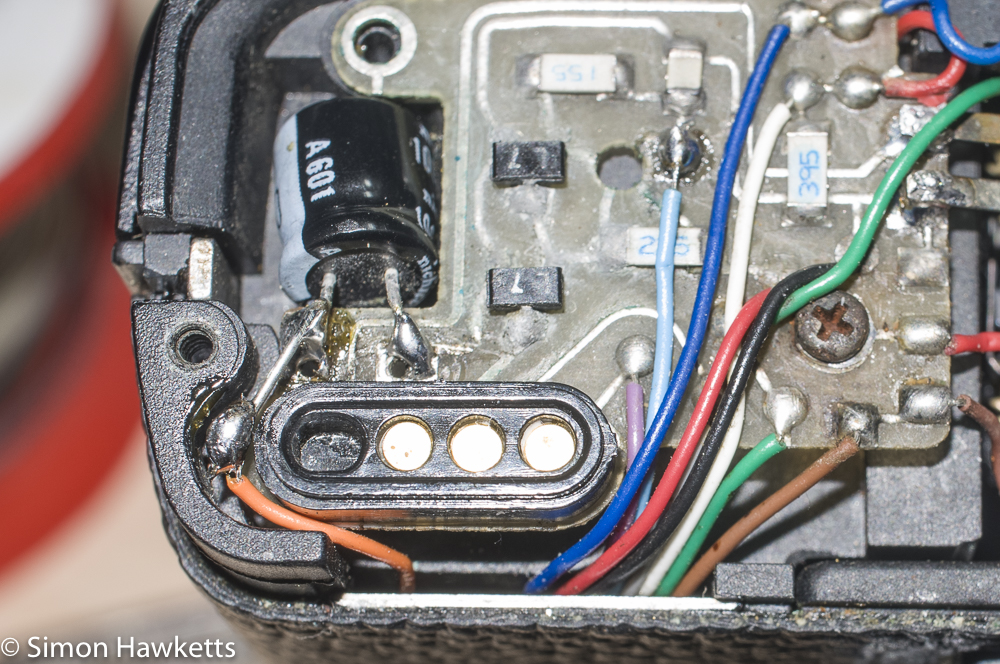
The symptoms of the problems with the XG-M were that the shutter wouldn't fire, although the metering seemed to work correctly. These are the details:
I fitted new batteries, and turned the camera on and tried touching the shutter button. With the camera in auto mode, the display in the viewfinder would display the shutter speed on the left-hand side of the display, but when I pressed the button, the display went blank and the shutter wouldn't fire. Because the shutter was cocked, the film advance wouldn't work, but if I took the bottom case off the camera I could mechanically fire the shutter using a small lever at the front of the body. If I set the shutter speed manually, it seemed to be firing at the correct speed, so it just seemed to be a problem with the electronics which triggered the shutter.
A bit of internet research suggested the problem could be some electrolytic capacitors which are fitted in various points around the camera. Over time, they start to leak electrolyte and become resistive. One is fitted in the compartment under the bottom cover, and three others are fitted to the PCB under the top cover. It was easy to see the capacitor under the bottom cover and sure enough, once I looked at it, I could see the tell-tail signs of green corrosion on the leads, so I could see it needed replacing.
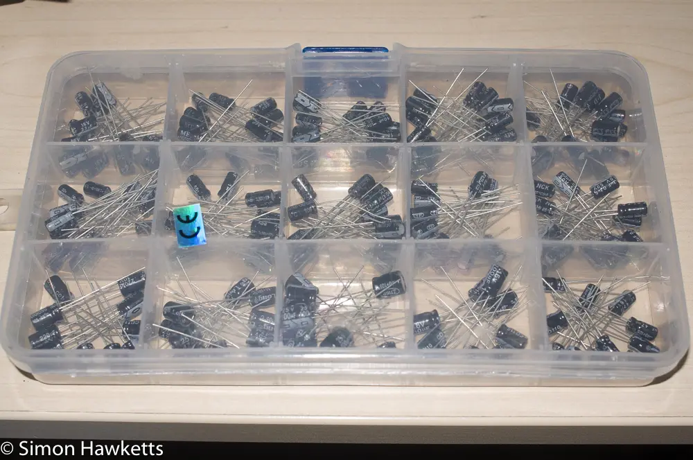
Since I don't have electrolytic capacitors, I sent for some replacements from China (200 assorted values for £3.20!) and waited for them to be delivered.
An important point to make about electrolytic capacitors is that they have a polarity - the light bar on one side indicates the -ve side and the other side is the +ve side. The new components must be soldered in the same way as the components you take out.
Once I had the box of capacitors, I could carry out the replacement. For the most part it is a relatively easy job apart from the fact that the components are small, and you are working in cramped conditions. The capacitor fitted under the bottom cover was really quite simple to replace. I just took the bottom cover off and found I could unsolder the old one and fit the new one without too much trouble. Because it's possible that was the only fault I tried the shutter again, but the fault persisted, so I knew I would need to also replace the top cover capacitors as well.
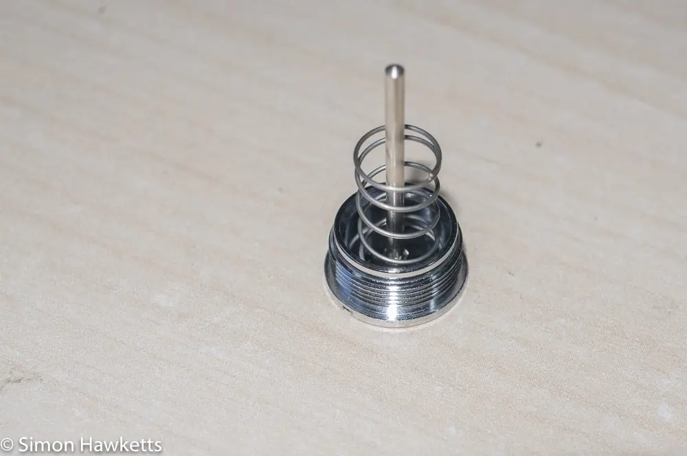
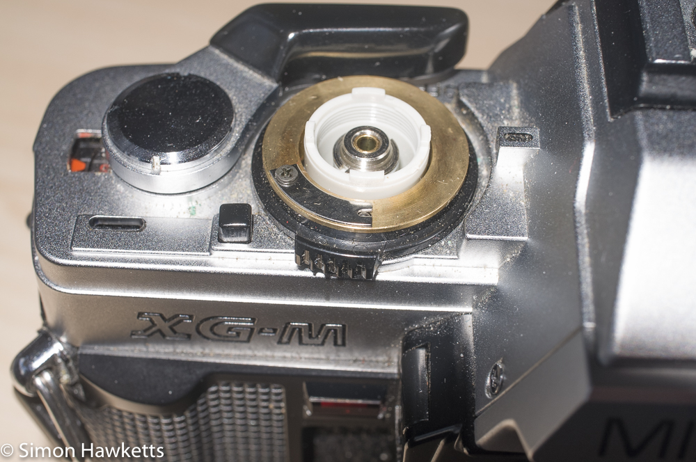
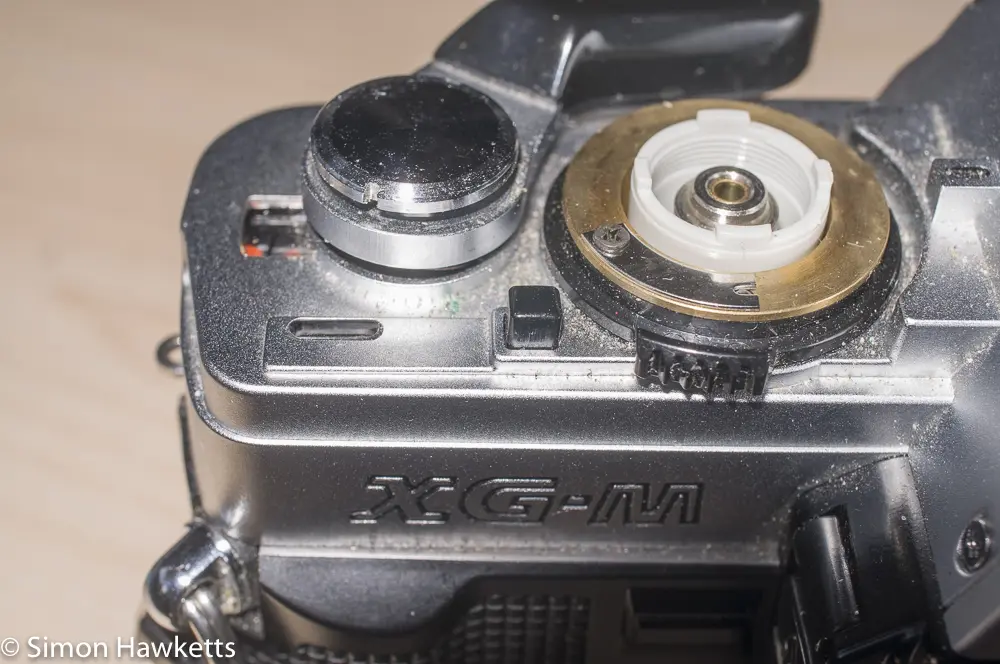
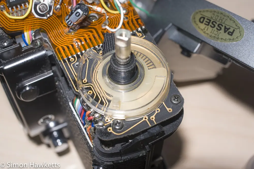
Removing the top cover on the XG-M was easier than a lot of cameras, but you do need to be careful at a few points. The ring which holds the shutter button down is actually finger tight so can be easily undone, but it is spring-loaded, so you need to be careful it doesn't spring up and get lost. Also, make sure you note the switch positions when you take things apart, so you can replace things with the correct orientation.
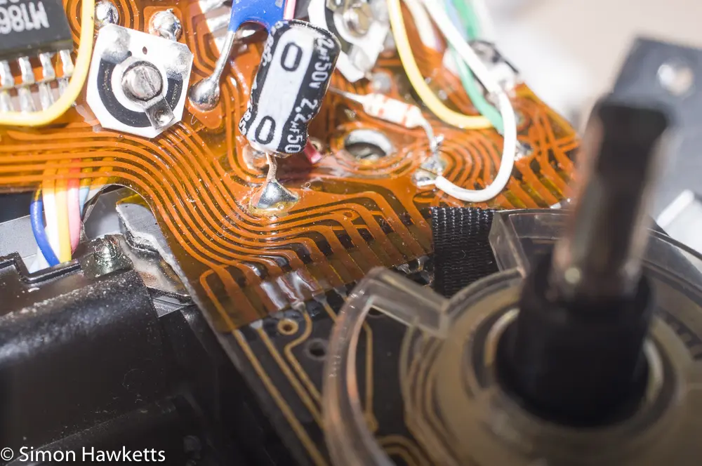
With the top cover off I checked the capacitors and sure enough the two under the circuit board had the signs of green corrosion on their leads, so I knew I would need to replace them. The one on the top of the board looked OK, but I decided to replaced it anyway because I didn't want to have to get the top cover off again after I'd refitted it.
The capacitor mounted on the top of the board was reasonably easy to replace. I just touched the soldering iron on the joints and pulled the capacitor free with a pair of tweezers. Then I cut the leads of a new 2.2uf capacitor to the same length and soldered it into the position the old capacitor occupied. I had to bend the legs a bit when I reassembled the top of the camera, but it was reasonably easy.
The two capacitors under the board were a bit more tricky. I found the easiest way to remove them was to cut the body off the old capacitor and remove it, so I could unsolder each leg independently. That was easier than trying to unsolder both joints and risk damaging the PCB.
I then cut the leads of the new capacitors to the right length and bent them, so they fitted in the correct position. This was the most difficult part of the whole operation because you need to hold the component in the right place as you also solder the leads to the board. Three hands are useful here! I managed this by just tacking the first lead in place with the soldering iron, using the old solder from the PCB to get it to stick, and then remaking the other joint with fresh solder and finally remaking the first joint. Another approach which may have worked would be to use a small pad of double-sided sticky tape to stick the capacitor to the board with the legs in the correct position, and then re-solder the legs.
Reassembly of the top cover was a bit tricky because the lock button for the exposure mode/shutter speed button tries to fall out of the cover. I found I had to offer up the cover on it's side and fit the camera in whilst also locating the viewfinder component, which also tries to fall out.
Once I'd got the top cover on, I tried the shutter again, only to find it didn't work! However, after a little investigation I found an orange lead which needed to connect to the same joint as the capacitor at the bottom had broken, so I had to patch it. Once that was done, my XG-M is working properly.

