In this post, I describe the final, working version of the 8mm film scanner which is a project I've been concentrating on for the last few months.
Change of Platform for the 8mm film scanner
It was several months ago that I last made a blog post on this site, and that post was a catch-up on the status of my 8mm film scanner project. Since that time I've been incredibly busy (something that I thought, now I've stopped work, wouldn't happen!) with household projects, Christmas and a variety of other things, but I have been able to make some progress with the project, and I now have a final iteration that I'm happy with.
I hesitate to say that the project is finished, because I suspect that time will never come; I do, however, have a platform that I can rely on to create still photographs of every frame of a film and that is a good basis for producing good video clips.
When I last wrote about the project, I said that I was intending to change the platform from the Eumig P8 I'd started the project with because I wanted a system that would work with both standard 8 and super 8 film, and at the time, I was looking at a Copal Sekonic 290 machine. As it turned out, I didn't in the end go with that machine because when I took a proper look at it, I wasn't convinced that the engineering quality of the film transport was good enough.
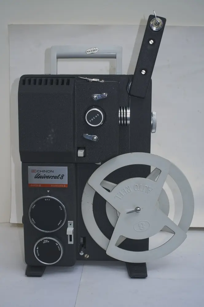
I wanted a chassis that has a reliable transport mechanism, and with enough space in the chassis that I could make a reasonable job of fitting all the electronics the project entails. In the end, the machine I went with was the Chinon Universal projector which I've had in my collection for a few years.
The Chinon Universal is a dual standard projector, made in the mid to late 1960s and the copy I had was in excellent condition, although I'd not been able to run it because I didn't have a mains lead for it. The important point was that the transport mechanism looked solid and reliable and is driven by metal chains, which implies longevity, and also the chassis seemed to have plenty of room once the motor and transformer were removed.
Before I embarked on stripping down the Universal, I first tested that the machine would auto feed and transport both a Standard 8 and a Super 8 film, winding the transport by hand to make sure the film would correctly feed though. Once I was sure the unit was OK, I proceeded to strip out all the parts that would be unnecessary in its new guise as an 8 mm film scanner.
Fitting sensors to the projector
One of the earliest changes I needed to make to the chassis was to fit a sensor to detect when the film transport has a frame of film ready to be scanned1.
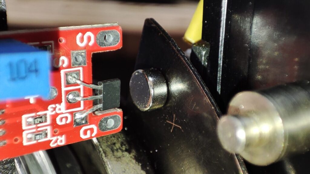
On the initial version of the machine using a Eumig P8, I'd fitted a micro switch into the frame advance mechanism that was switched at the point a frame was ready, but it was fairly apparent when I looked at the Chinon Universal that I wouldn't be able to follow that approach, because there was nowhere I could see that I would be able to fit a mechanical switch. Because of that I decided to use a hall effect sensor on this version.
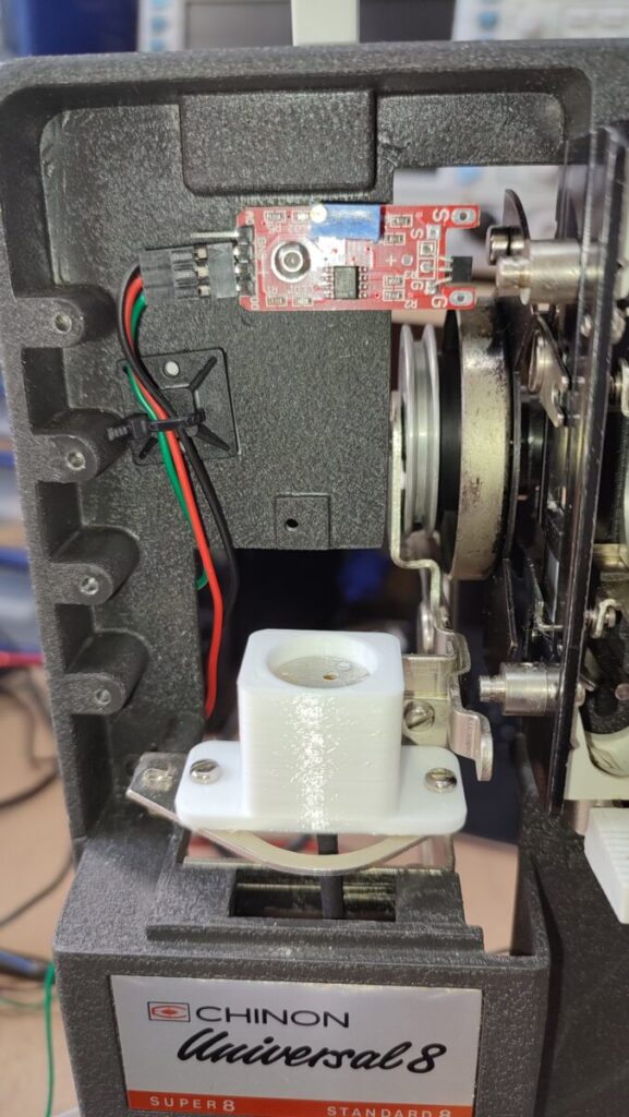
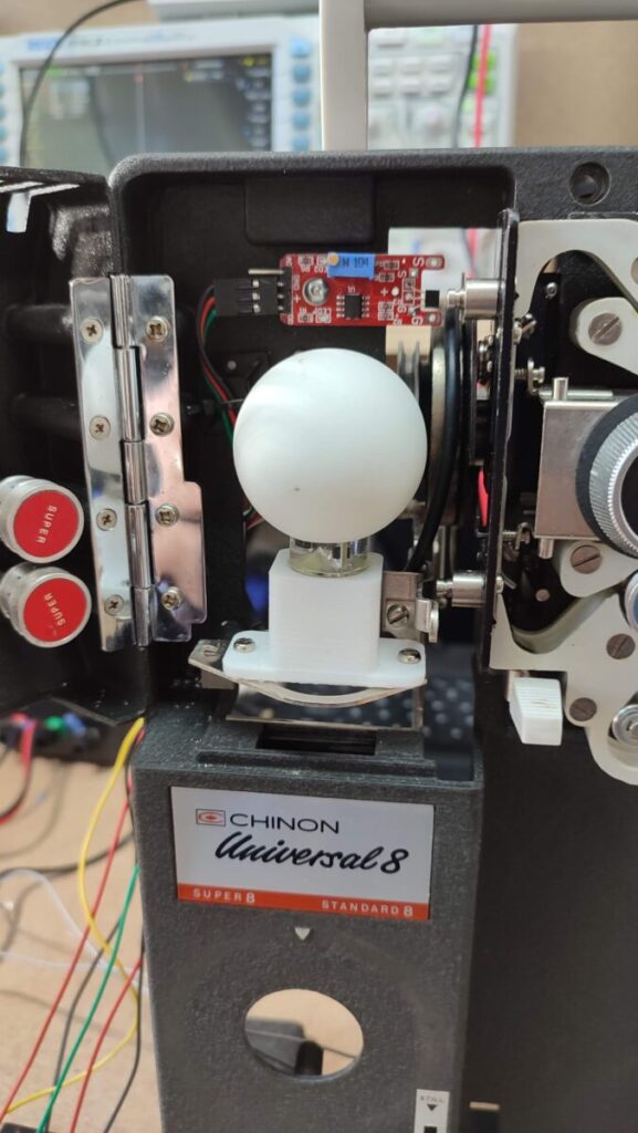
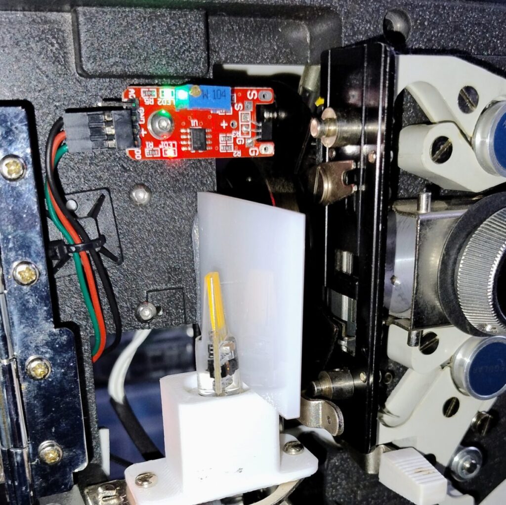
A Hall effect sensor is a device that can detect the presence of a magnetic field, so I fitted a small PCB with hall effect sensor just inside the lamp housing, and super-glued a small magnet onto one of the shutter vanes.
The Chinon Universal has a three blade shutter so I worked out which one would be in the correct position to trigger the sensor when the film frame had just been pulled into place to work out where to fit the magnet.
The sensor PCB has a small pot which allowed me to adjust the sensitivity once the unit was all assembled, and by adjusting the pot and positioning the magnet, I got the timing set up correctly.
Once the frame detect sensor was fitted, I looked around the chassis to see if there were other things that would be useful to detect and I found two other places to fit sensors.
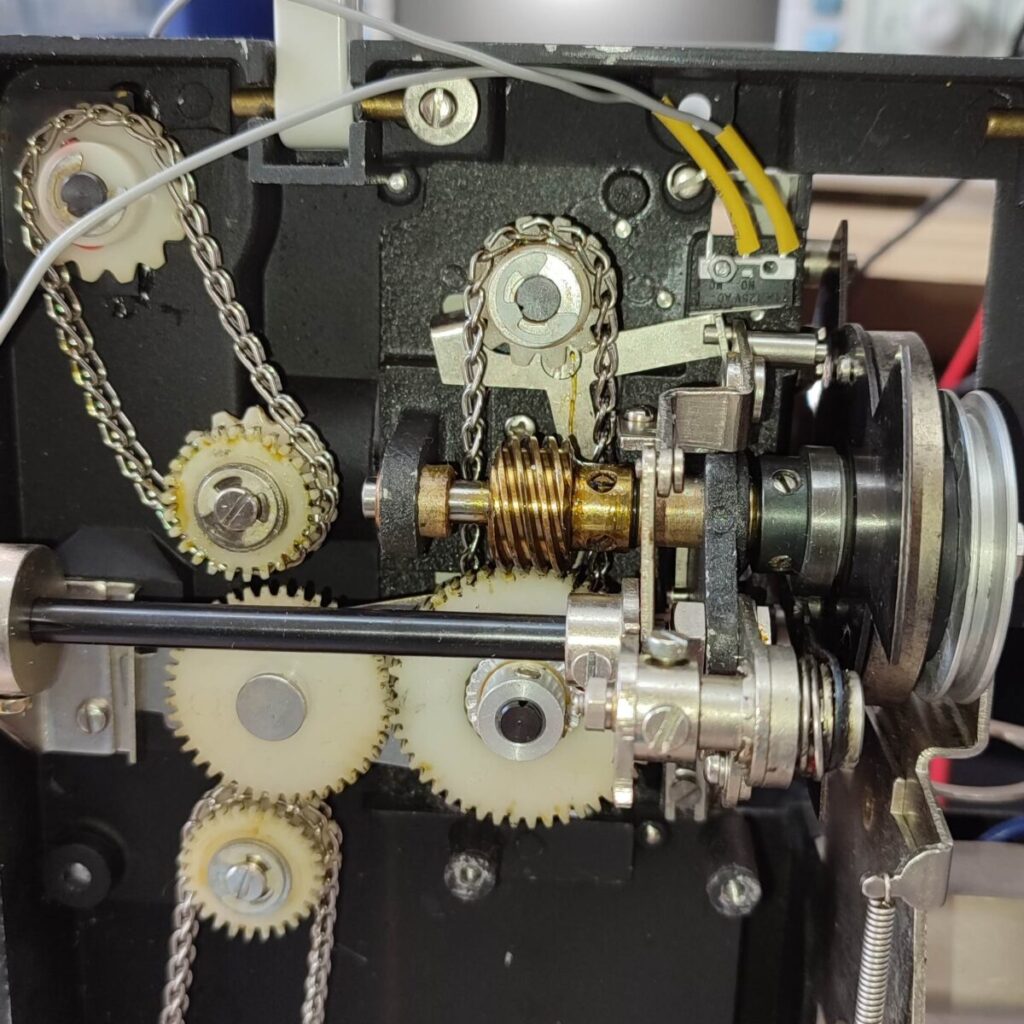
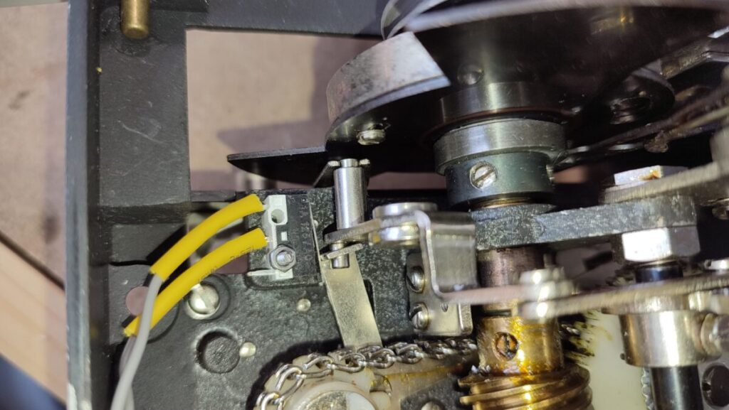
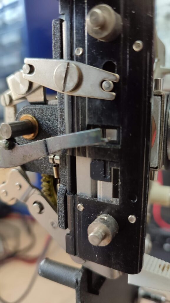
First, I fitted a small micro switch in the film transport that is activated when the standard 8/super 8 switch is changed, so I can read the film format. This sensor is shown in the photo here.
I then fitted another hall effect sensor to a small arm which is moved when the film is pulled onto the take up reel.
This sensor is used to detect when the machine is correctly loaded with film, so I can use it to make sure the telecine process stops if a film breaks (not an unusual event with vintage films), or when the film naturally comes to the end.
Fitting the Motor and other electronics to the 8mm film scanner.
With the sensors fitted I then proceeded to fit the other electronics and motor to the chassis.
I found there were quite a few fixing holes that the original motor and transformer had used which I could utilise to fit the raspberry pi, a buck convertor PCB to supply power for the raspberry pi, the stepper motor, motor control board and lamp to. For most of these components I designed structures to use the mounting holes and printed them with my 3D printer. Although I had no real experience of 3d design, I found that once I'd worked though some basic shapes and simple tutorials, I could use FreeCAD to create the parts needed.
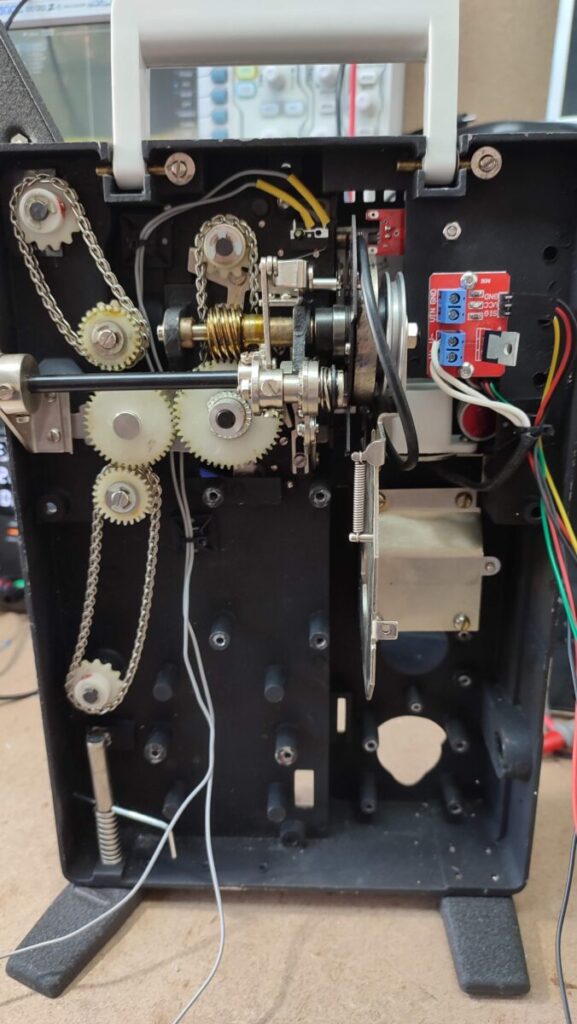
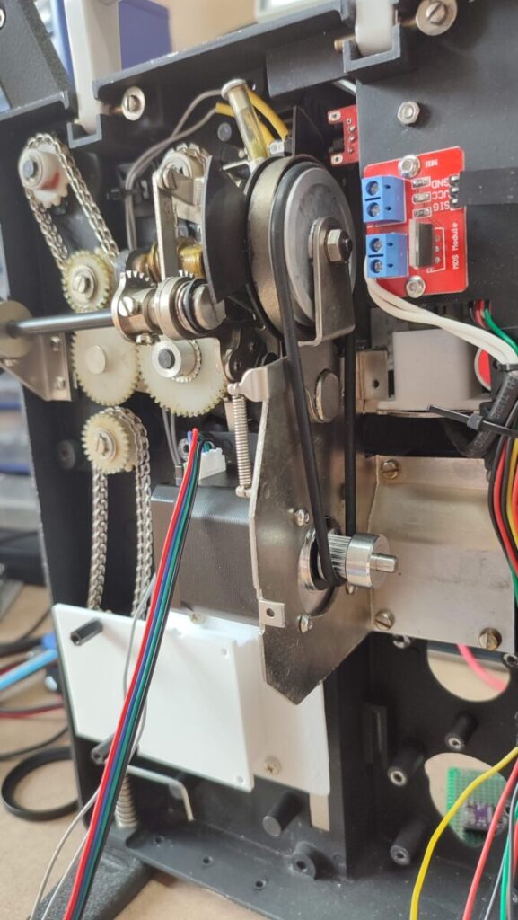
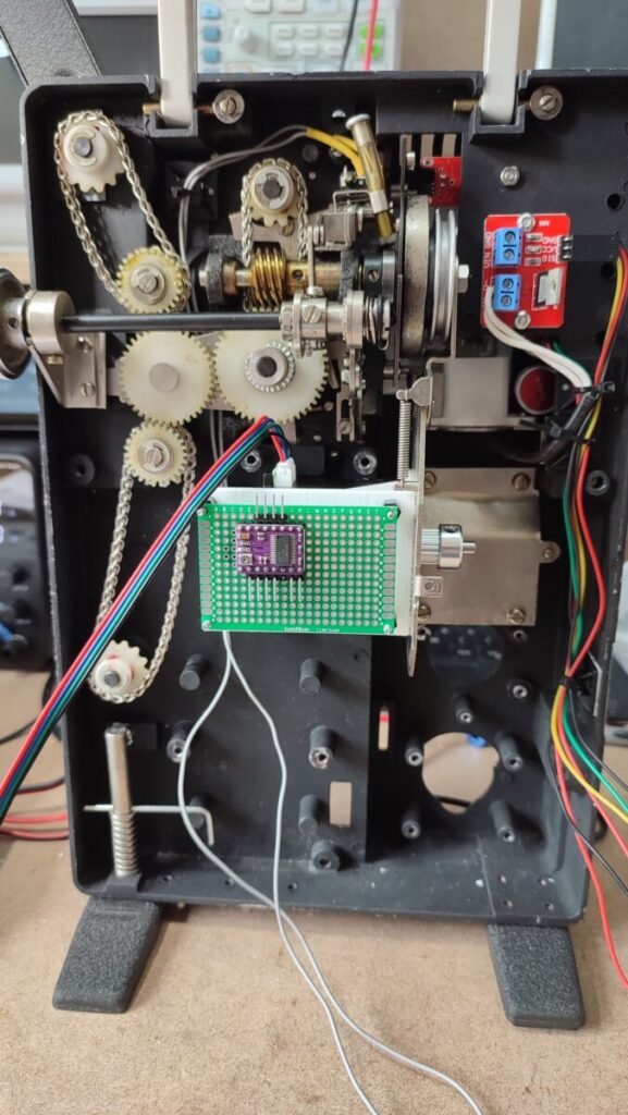
The layout of the new film scanner can be seen in the photo shown here.
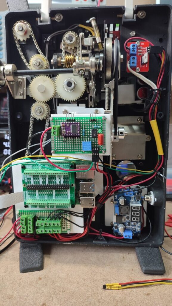
The 12 Volt power is fed into a socket in the side of the unit, and next to the power socket is the DC to DC Buck Converter board (with the 888 display which shows the OP voltage) which produces the 5 Volt supply for the raspberry pi.
To the left of the Power board is the raspberry pi, with an I/O header board fitted to it, and a power distribution PCB underneath which feeds either 12 V or 5 V to the different parts of the machine which need the power.
In the centre of the picture is a home made board which houses the motor control circuit, and an op-amp comparator which is used to detect changes from the hall effect sensor that detects when film is loaded onto the machine.
The stepper motor is mounted behind this board and can just be seen to the right, with a belt which drives the film transport mechanism above it.
At the top of the unit is a small PCB which switches the power to the lamp.
For the lamp replacement I used a 2W, 12 V LED and designed a small 3D printed holder that fitted in place of the original lamp holder which held the LED at the correct height for the film frame. Initially I fabricated a light diffuser from a ping pong ball which actually gave reasonable results, but I have since purchased a small sample of Plexiglas which is designed to be used as a light diffuser, and I'm redesigning the lamp holder to incorporate it2.
Optics and Camera used in the 8 mm film scanner
The most difficult part of the construction was the placement of the camera which has to be precisely located in front of the film and with a very high magnification lens in order to take a high quality image of each frame of the film to later assemble into the video clip.
The camera used is a Raspberry Pi high quality camera which is fitted with a C-Mount lens mount that allowed me to try different lenses and extension tubes until I found a combination that worked.
In the end, I used a Schneider Kreuznach Componar-C 75 mm f/4 enlarger lens mounted on a 90 mm extension tube and using a c-mount to M42 adaptor. The lens is actually M39 screw thread, so there is an M42 to M39 mount adaptor fitted to the lens.
Many people who have made similar scanners have used a 50 mm lens, and I also tried to use a 50 mm3, but the design of the Chinon Universal meant that a 50 mm lens couldn't get close enough to the film plane to give a 1:1 macro image.
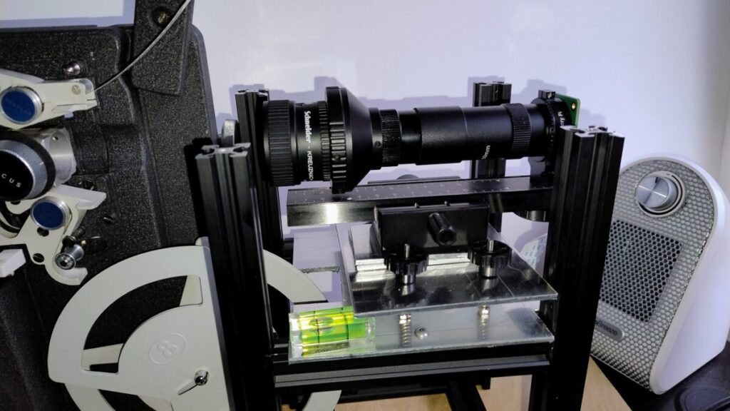
I tried lots of different methods of mounting the camera, but in the end settled on a framework made from aluminium extrusion, of the sort used to construct 3D printers.
I bolted together a frame, and then used aluminium sheeting to create a platform that the camera could sit on. Initially, I tried to get this platform to the correct height for the camera, but later added a second platform above it and used bolts, springs and thumb-wheels to create a levelled platform that could be adjusted for height as required.
The camera module itself is mounted on a movable mount with a adjuster knob which moves the camera towards or away from the telecine machine. Using this knob allows me to fine focus the image of the film frame.
Changes to the software for the 8 mm film scanner.
In the last iteration of the film scanner, I'd rewritten the software to use a newer UI toolkit and I kept most of these changes in place, but instead of having the application run on the raspberry pi, I changed the operation of the machine so that the app runs on a laptop computer and the 8 mm film scanner just runs a REST API which is given instructions to carry out the basic operations needed to scan the film.
So for example, there are commands to run the motor, turn on the lamp, stream the camera, capture a frame etc, and the application that runs on the laptop is responsible for sending those instructions.
There are several advantages in structuring the software in this way, the most obvious being that the most complex operations are carried out on a more powerful machine than the raspberry pi which is left only carrying out the simpler hardware control etc.
Controlling the video quality
In order to allow control of the quality of the final 8mm film scanner result, I created a python class called ScanningProfiles which controls the resolution of the images taken, and the number of images for each film frame.
For example, a film can be scanned at 640 x 480 with one image per frame at the lowest quality setting, or at the full resolution of the camera (4056 x 3042) with 5 images per frame (at 5 stops under exposed, 3 stops under exposed, correctly exposed, 3 stops over exposed and 5 stops over exposed) which are merged to produce a single image at the highest quality. These scanning profiles can be selected when starting a film from a drop down list in the UI.
The obvious compromise when deciding the quality is the time it takes to scan the film - low quality is relatively fast and high quality is relatively slow. I've found that for most films, the best compromise is to use Full HD resolution with 3 images which runs at about 20 frames per minute - this equates to about 1 minute to scan the number of frames that make up 1 second of film - therefore a 3 inch reel of film takes about 4 hours to scan.
Another aspect I found I had to deal with is determining the correct exposure for the level of light I'm using. I found that if I use a fixed shutter speed of 80 ms on the camera and stop the lens down to F/11, this gives me a correctly exposed image if the film is correctly exposed.
I then have a compensation control on the software UI that allows me to increase or decrease the exposure by up to 5 stops to compensate for films that are poorly exposed.
Dealing with cropping and straightening the image.
I had hoped that with the camera fixed in place in front of the projector I would be able to set it completely straight in relation to the film frame, but in practice this has been very hard to do. Because of the very high magnifications involved, I find that the film frame is always off the horizontal, so I decided to fix that in the software.
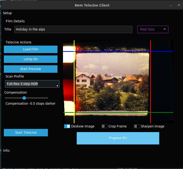
As each image is taken, a low resolution copy is sent to the UI program which is displayed to show the latest image. I've set up a right-click menu on this component which lets me set two points called 'Skew points' which have a line drawn between them. I set this line to line up with the frame and then I can use the line to calculate the amount the image is skewed from horizontal and apply it to the image.
The menu also has the option to set top, bottom, left and right marker lines which can be used to crop the image and remove the unwanted sprocket holes and space around the image. This can be seen in the image shown here where the blue, yellow, red and green lines represent the top, left, right and bottom of the wanted area.
As well as the actual program that runs the telecine process, I've also written some scripts that produce a video clip from the captured images and crops and de-skews the images at the same time.
Some other images of the 8mm film scanner
This gallery contains some other images of the machine as it was being built.
Machine in operation
The two very short videos below show the telecine in operation - first the machine running and secondly the software UI as it scans a film. I may make a longer version which shows the machine in more detail later.
Telecine result
The film below shows an example of a film which has been digitised using the 8mm film scanner. It is straight from the machine, with no form of post processing, so there are still issues with it, but it shows that reasonable quality results can be obtained (although this film does have some sections which have been fogged so it's possibly not the best film to show off the capabilities).
8mm film scanner Conclusion
My main aim when creating my own 8mm film scanner was to produce better results than I obtained with the machine I purchased from amazon and I've certainly achieved that.
But along with better results, I also have high definition images of each frame of the film, which mean that I can work on the software and improve the results - the original machine only produced a highly compressed video file that couldn't easily (or probably at all) be improved.
- Actually photographed since that is the basic method of converting the film to digital - take a photo of each frame of film and then assemble the individual photos into a video clip [↩]
- At the moment, I've glued a section of the new diffuser in place between the lamp and the film gate and it seems to be giving good results [↩]
- which would have resulted in a smaller extension, and therefore would be less bulky [↩]
Superb work Simon, well done!
Thanks Nigel
So good. I am still working very full time, but have a couple of projectors & many family cine films from the 60's & 70's that will get attention when I have some bandwidth to do a similar project. Thanks so much for the inspiration & sharing ideas for realisation of the project.