My useful 9.5mm scanner for amateur cine film
This post is an update on the progress of my telecine project and describes how I made a new 9.5mm scanner to join the original standard 8 and super 8 model.
It was about 6 months ago that I last posted an update on the progress of my cine film scanner in a post titled ‘Final iteration of my 8 mm film scanner‘. Well, I’m back with another update because I’ve made lots of changes that I thought might be interesting to anyone who is considering a similar project, including adding a new model to my film scanning arsenal, a 9.5mm scanner.
Summary of changes to my cine film scanners.
I’ll list the changes I’ve made and then go through each in a bit more detail in the rest of this article.
- Changed the UI toolkit to QT5.
- Improved the mechanical construction of the camera unit.
- Moved the telecine machine and the camera into separate projects to allow for the 9.5mm scanner
- Moved the telecine machine from being raspberry pi based to using an ESP-32 microcontroller.
- Added local controls, better construction and re-engineered some parts.
Changing the UI toolkit to QT5
I decided to re-write the UI using QT because QT provides a brilliant UI design tool called QTCreator, which not only allows very rapid changes to the UI layout to be produced, but also decouples the code for the UI from the rest of the film scanner software.
In the last iteration of the cine film scanner, which used a rather old and outdated toolkit called ttk, all the code which creates the UI components was part of the main program code and had to be altered to move elements about or replace them1.
I spent hours refactoring code to get the layout right, and then if I wanted to add another component to the UI I had to start refactoring again. I worked out that the change to use QT would probably only take a couple of days and it would be worth doing for the ease with which I could then make alterations to the user interface.
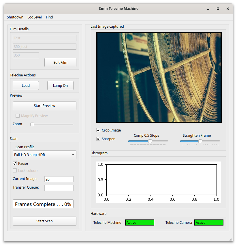
As it happened, I got the code converted to QT in a morning, so that is something that has definitely paid off. When I look back at the UI from my last post and compare it to the current version (shown here), I realise it would have taken many months to produce a similar level of functionality with the old TTK based toolkit – in fact the richness of the QT toolkit probably means I would not have been able to code some elements, like for example, the histogram display.
Some of the other changes that have happened on the UI code, which is the code that basically controls the scanning process are:
More film details are now recorded like the film manufacturer, colour/black & white, approximate subject date etc. The preview process now has a magnify/zoom function for easier focus, there is a function to straighten the frame as the film is being scanned, a histogram is produced for each image to check the exposure and there is better management of the camera colour gains to get the best colour match to the original film.
Better mechanical construction of the camera unit.
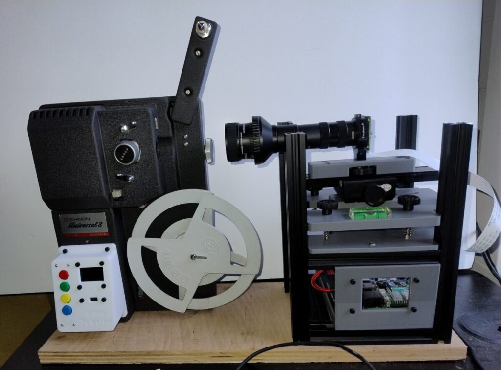
The camera unit on the last iteration was a bit Heath-Robinson, with the camera mount plate being constructed from sheet aluminium. Because I needed to mount a raspberry pi on the bottom of the camera unit (for reasons I’ll come to later), I designed some pieces to carry the raspberry pi, a power regulator board for it, the camera and it’s floating plate arrangement with FreeCad, and printed them on a 3D printer.
Although this has resulted in a much more solid design, and one that is easier to use, the printing process was a bit fraught with problems and took several iterations to get right2.
Creating the 9.5mm scanner
In order to create a 9.5mm scanner, I separated the cine film scanner and the camera unit into separate projects.
The last iteration of the cine film scanner was working well and I had no real problems with the whole unit being controlled by a single raspberry pi, but having decided to create a unit for 9.5 mm films and, eventually, 16 mm films it made sense to separate out the camera from the film transport.
If I had just replicated the original design for 9.5 mm, I would have to buy another camera unit and raspberry pi controllers for each separate machine which would have come to about £120 each unit, so I took a different approach.
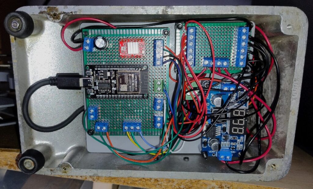
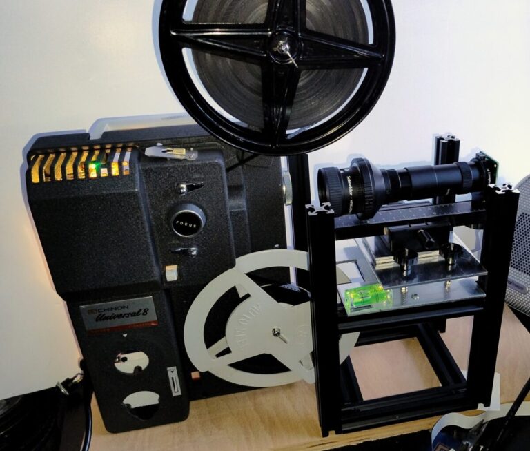
I kept the raspberry pi controller for the camera unit, and re-designed the telecine part to use a cheap ESP-32 micro-controller. This way, I could create machines for other cine film formats, and use the same camera unit with each device, just changing the size of the extension tube to change the magnification level of the camera. Since an ESP-32 micro-controller is about £10 that’s a significant saving from buying a raspberry pi for each scanner.
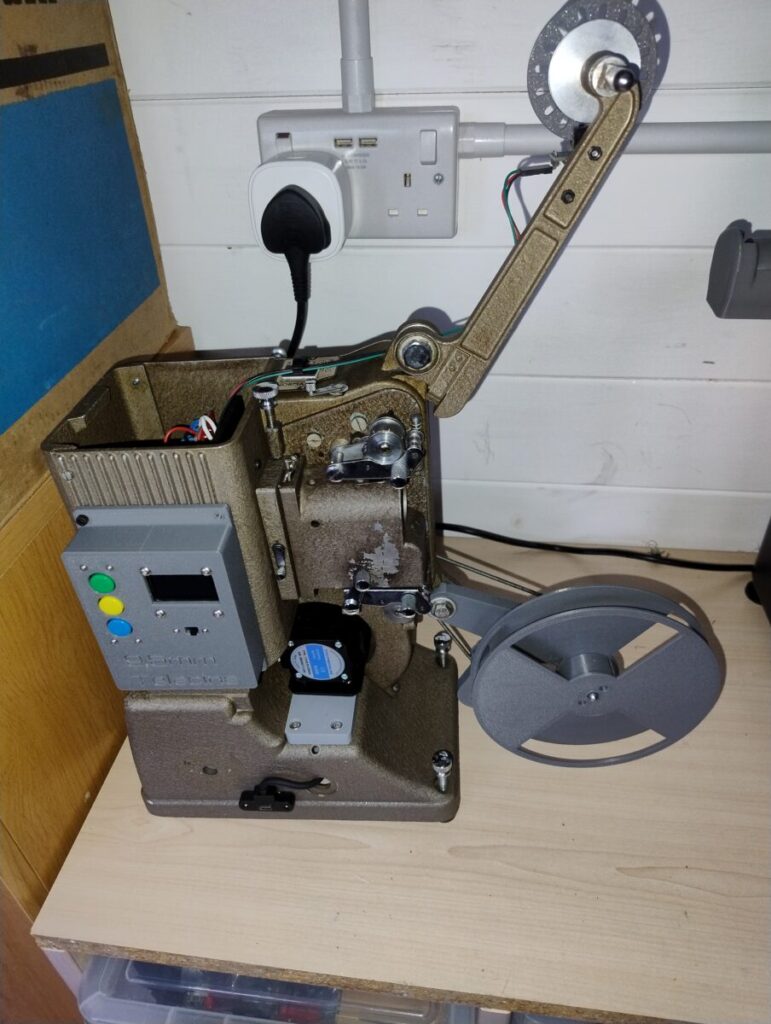
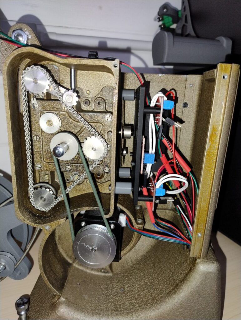
So far I’ve converted the super 8 / standard 8 Chinon machine I originally built to use an ESP-32, and I’ve added a Specto 500 9.5 mm machine to the stable so that I can scan 9.5 mm films.
In fact once I started work on the Specto 500, I realized that the sprockets and film frame were replaceable and the unit I have is actually a dual standard 9.5/16mm unit although I didn’t have the 16mm parts of the kit.
When I’d made this discovery, I looked on eBay to see if I could find a set of 16 mm sprockets, and managed to find a seller on eBay who was selling what they described as an ‘old 8 mm projector’ but once I’d examined the photos it was apparent that they were actually selling a 8mm / 16mm Specto 500 which had the 16mm sprockets on.
I bought managed to buy that for only a few pounds and was happy to find that the 16mm sprockets fitted my machine and so I now have a 9.5 mm and 16 mm film scanner as well.
Of course moving to the ESP-32 platform meant that some of the python code I’d written for the telecine had to be re-written in C++, but that actually turned out to be not too difficult because there are libraries written for most of the hardware interface, so it was just a question of brushing up on my C++, which I last used in the early 1990s (Borland Turbo C++).
Other enhancements and changes to the film scanner
Film complete sensor
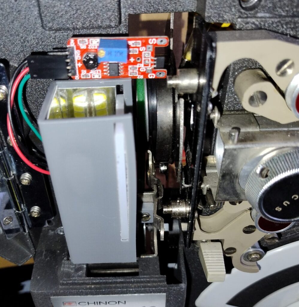
The original idea for a sensor to detect the end of the film didn’t work as well as I’d originally hoped, and couldn’t be replicated on the 9.5mm scanner because, being a much earlier design and therefore much simpler, the Specto 500 had nothing that detected when the film was loaded onto the machine.
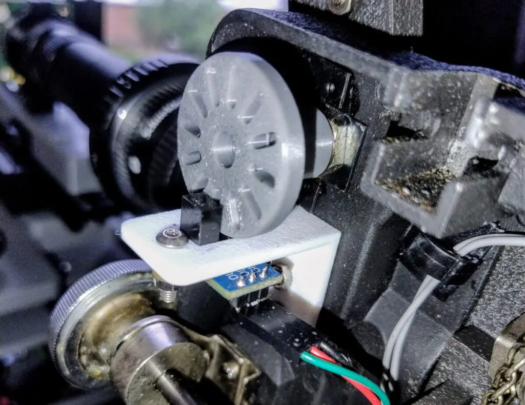
I tried to implement a light path sensor that would have the film passing through it and detect when it was missing, but that idea didn’t work because the film didn’t trip the light path3.
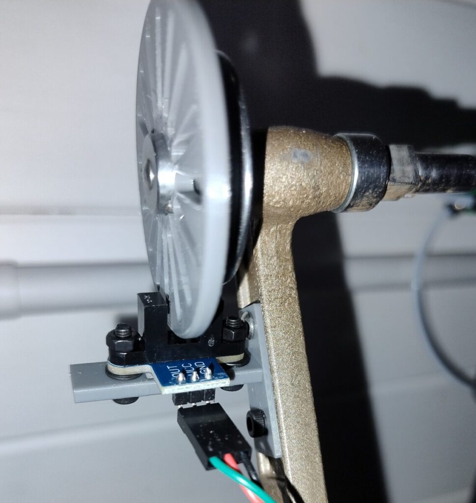
In the end I found the answer was to use the light path sensor to detect when the feed reel for the film stopped turning. I did this by adding a perforated wheel to the take up reel on both machines and then set the light path sensor so it’s beam was interrupted by the wheel turning.
Although the wheel turns very slowly, especially at the start of the film where it takes about 15 frames before the beam is interrupted, it’s enough to sense when the reel has stopped turning and therefore the film is finished.
Local controls
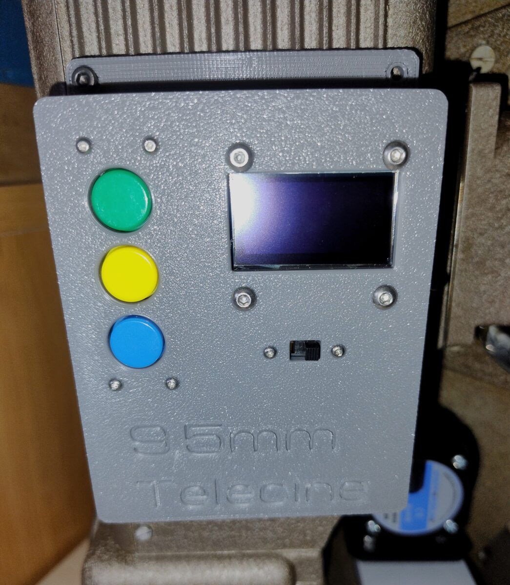
I found that having to use the UI software to turn on the telecine motor and etc was a bit of a pain, so I added a 3D printed front panel with some push buttons on to allow me to turn on the lamp, run the motor and advance the frame straight from the scanner itself.
I also added a small display to each unit which shows the IP address and some basic information about the unit’s progress.
Improvements to the light source
I made some improvements to the light source by using PCM to control the brightness of the LED and designing a better holder for the LED and diffuser. This allows me to use changes in the light source to produce multiple exposure images which can be merged to produce a simulated HDR image. Before I used changes in shutter speed on the camera to do this, but this was resulting in some very long exposure times if the film was under exposed.
Sometimes old films aren’t rewound
I found that sometimes the films I’ve found on eBay haven’t been rewound so that the start of the film is not the end emerging from the reel. Because this became a common occurrence, and I found I was scanning films that were upside down and backwards, I added an option in the UI to flip the image and assemble the individual images backwards to make the video clip rather than forwards. This is actually quicker than having to rewind the film sometimes.
Video of the 8 mm film scanner working
This is a short video of the Chinon 8mm film scanner running
16mm / 9.5mm scanner in operation
This short video shows the Specto 500 9.5mm scanner with a 16mm film.
Sample 16mm film from the scanner
The film that follows is one of the first 16mm films I’ve scanned with the new scanner, just to give an idea of the sort of performance it can achieve.
Upcoming Changes to the film scanners
I have some more updates planned over the coming months which I’ll note here.
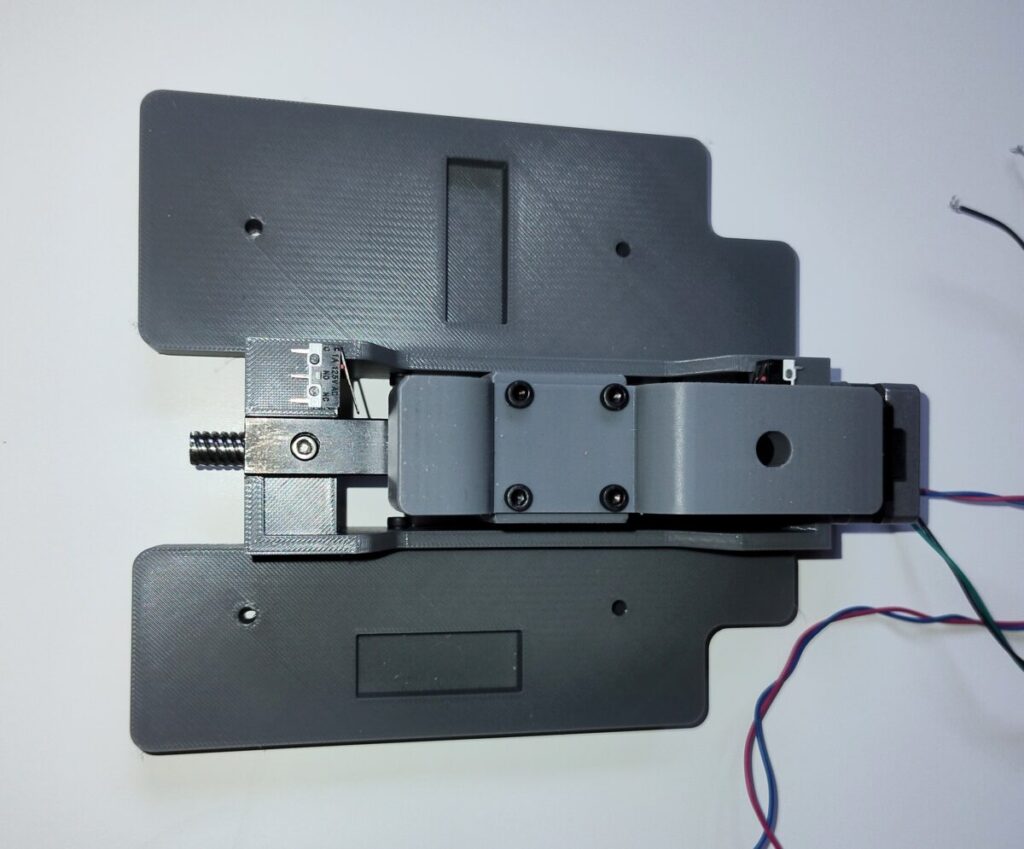
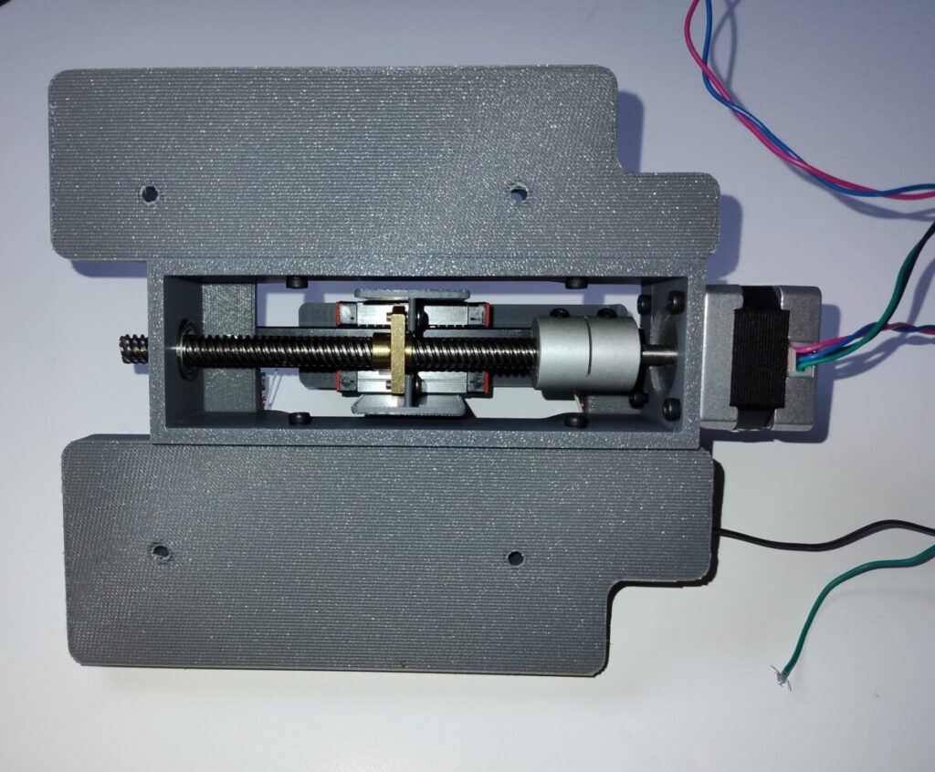
First I’m redesigning the camera module to add a stepper motor to the focus setting so that I can focus the camera electronically. Although it is easy enough to adjust the focus manually, I want to be able to adjust the focus remotely if I find the image is starting to drift. This would be particularly useful during the winter months when I’ll probably have to have the scanner in the bedroom and monitor the results from downstairs.
To add the stepper I used some threaded rod from an old Ender 3 3D printer and a short linear track that the camera sits on to allow it to smoothly move backwards and forwards.
Another idea I’ve had is to try to deal with large changes in exposure that I’ve noticed on several films. I always use a fixed exposure on the camera rather than auto exposure so that the image doesn’t vary from frame to frame. That basically works, except when there are large variations in the exposure level of the film – some films move from outdoors to indoors and the film may move from being a stop or two over exposed to a stop or two under exposed.
The only way I can see this is if I watch the process all the time, but that isn’t really possible. I have thought therefore of having a two pass process where the first pass is run at low resolution and as quickly as possible to get a measure of the exposure of each frame4.
This run would record this data in a local SQLite database, and then the second run would be the high quality scan which would use the database to set the correct light lever / exposure value
Some photos of the film scanners.
- although I know I could have restructured the code to make the UI class separate, the QT tools do this automatically which makes things simple [↩]
- Although during this project I upgraded my 3D printer to a bambulabs P1S and that has made an enormous difference to the quality and speed of the printed components [↩]
- I didn’t expect the clear parts of the film to trip the light path but I was surprised that even completely dark film didn’t do anything [↩]
- or possibly of every scene change [↩]
Discover more from Everything Vintage
Subscribe to get the latest posts sent to your email.
