Joseph Baker single valve radio c1922
This is a bit of a departure for me in that although this post is about a vintage item it’s not a vintage camera but instead a vintage single valve radio. This post features a radio receiver or wireless which was made in about 1922 by a manufacturer in the town where I grew up (although that was a long way past 1922 I hasten to add).
Single Valve Radio images
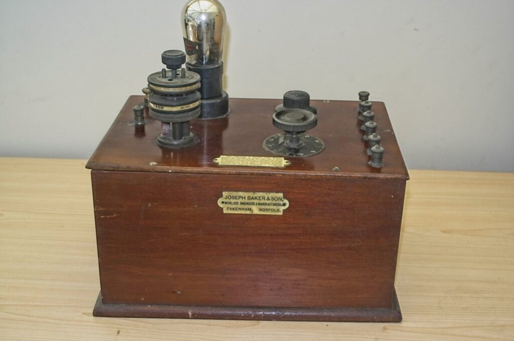
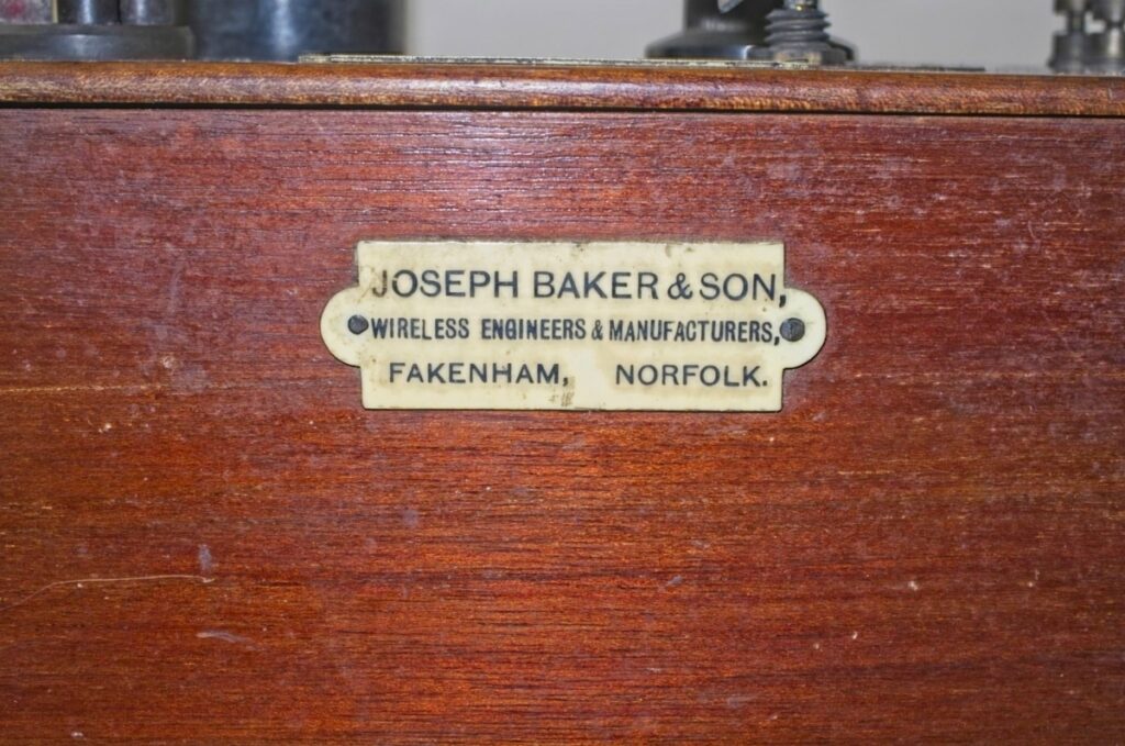
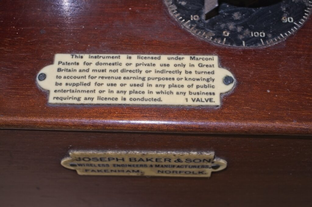
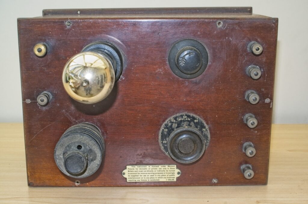
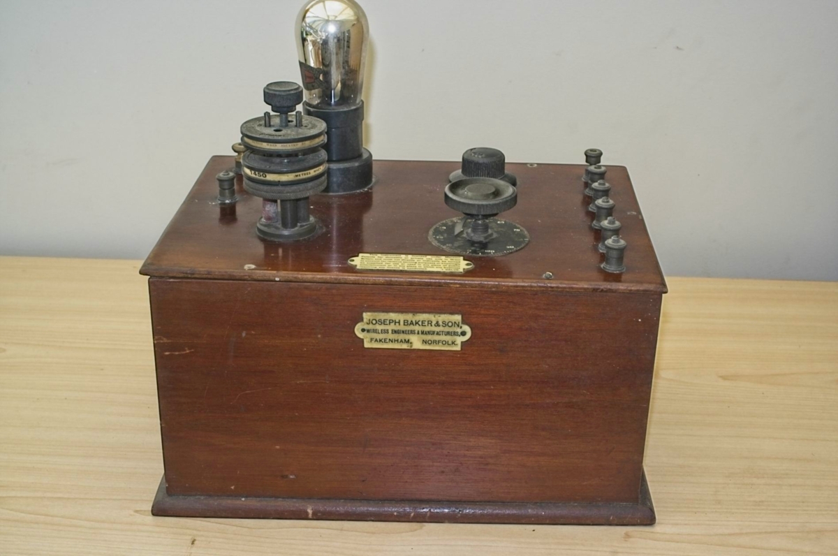
The Joseph Baker Single valve radio
This single valve radio is not actually mine. At the moment I have it in our house simply because my mother is moving from the house she moved into with my dad when they got married in 1953, and I’ve taken it to our house for safe keeping while the move takes place.
The radio was purchased by my Dad many years ago and he bought it because it was made in Fakenham where he was born and lived his whole life. I have no idea what he paid for it, but I suspect it was not too much money; he probably bought it at the time it was just an old radio rather than a vintage, and therefore more valuable, radio.
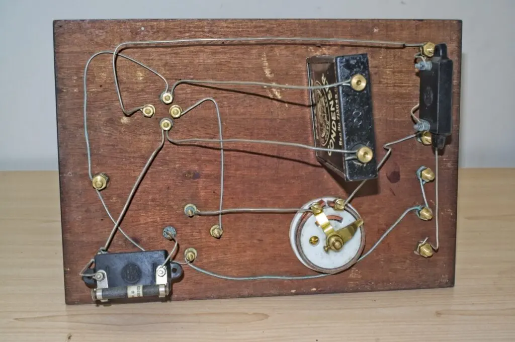
The radio design is remarkably simple.
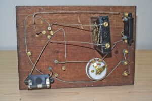
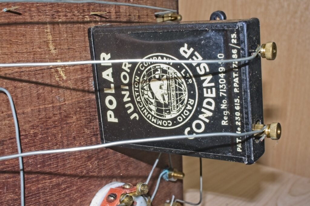
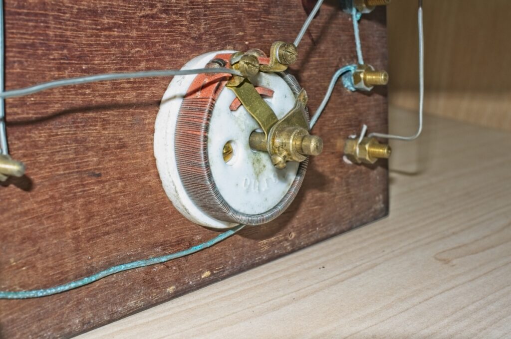
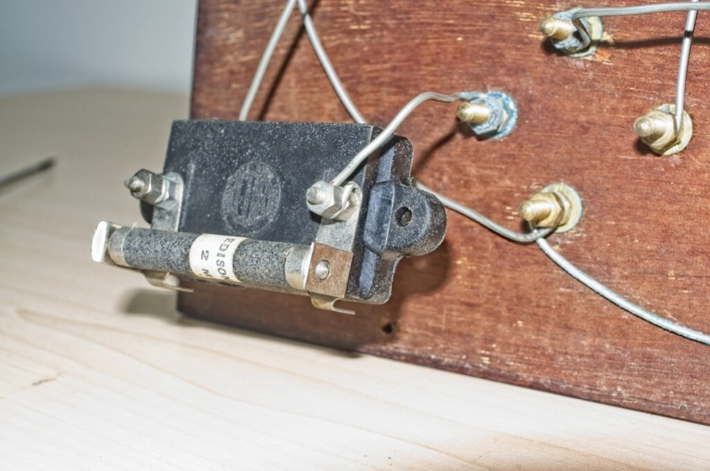
As the photo of the wiring shows, there are virtually no components in the set other than the valve itself, a tuning circuit consisting of a variable capacitor and a coil, a rheostat (variable resistance) and a couple of capacitors.
The set would have worked as a TRF unit, or Tuned Radio Frequency receiver.
The single valve would have acted as both an RF amplifier and a detection circuit and all the power would have been supplied with external batteries.
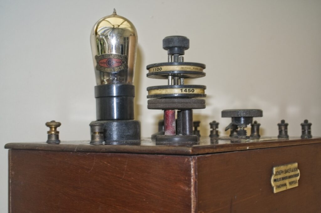
In fact, if you look at the picture of the top of the set you can see there are a large number of terminals. The two on the side of the valve and coil would be aerial and earth, while the set on the other side would be used to connect a low tension supply for the valve filament, a high tension supply for the valve anode circuit and a set of high impedance headphones would have been connected to the other set to allow the user to listen to broadcasts.
Using the Radio
In order to use the radio the user would need to erect a long aerial, probably the length of their garden and as high up as possible, as well as an efficient earth connection. The earth often consisted of a copper plate buried in the ground with a wire brought up to the set.
With the aerial and earth connected and all the voltage supples wired to the correct terminals, the user would then put the headphones on and try tuning the set.
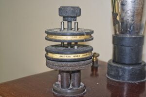
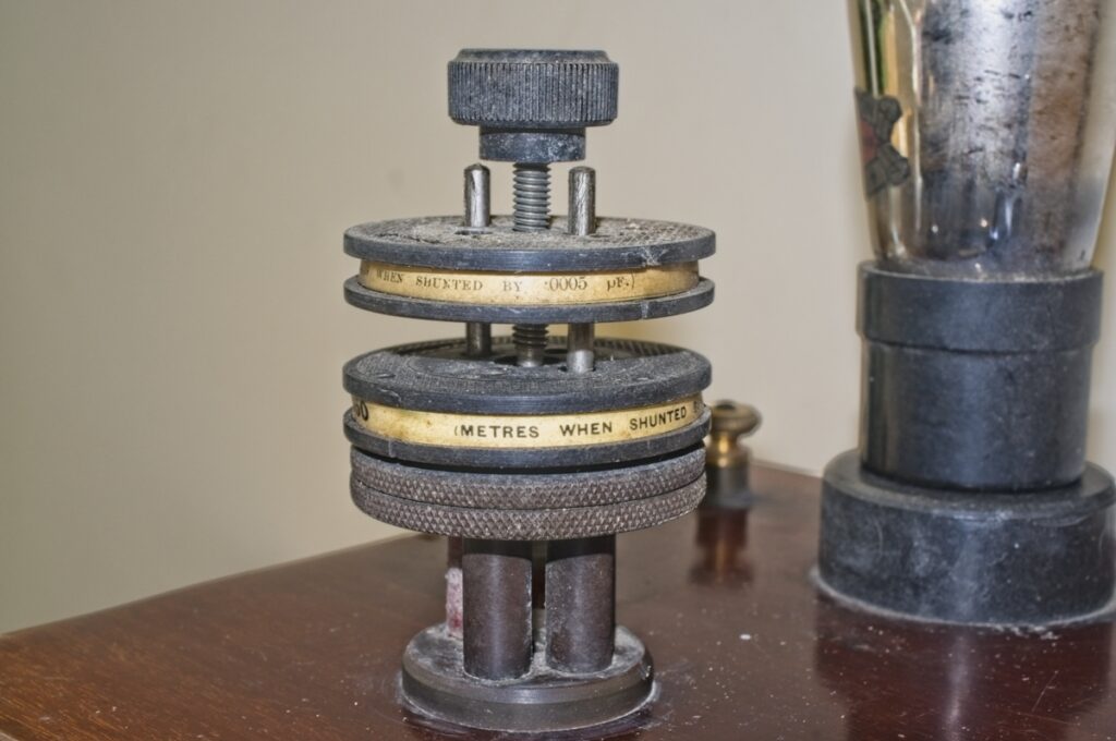
To tune to a particular broadcast the correct coil would need to be fitted (you can see on the coil an indication of the wavelength it tunes to and the socket the coil is plugged into) and then the variable capacitor is slowly turned whilst the headphones are listened to until a signal is heard.
Once the signal is obtained, the control on the top of the coil can be slowly wound down to improve the receiver’s gain. This control moves the top coil closer to the bottom coil and implements what was called ‘reactance’.
Basically one coil is in the input (or grid) circuit and the other coil is in the output (or anode) circuit and as they are brought together the feedback between the two increases which also increases the gain of the circuit. This increase in gain will result in a louder, clearer signal, but if the coil is brought too close the circuit breaks into oscillation – a loud squeal is heard in the headphones and worse still the radio becomes a transmitter and blocks anyone else trying to tune the same frequency. This would not go down well with any neighbour who was trying to listen!
Although I have never heard this particular set working, I do remember when I was a boy making several sets using similar components which my dad had laying about in his workshop and writing this piece has brought back many memories of those times.
Discover more from Everything Vintage
Subscribe to get the latest posts sent to your email.

