Miranda Fv TTL viewfinder repair.
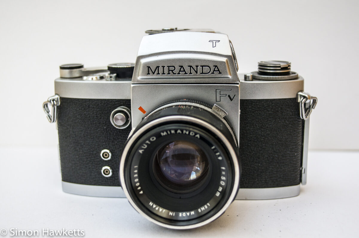
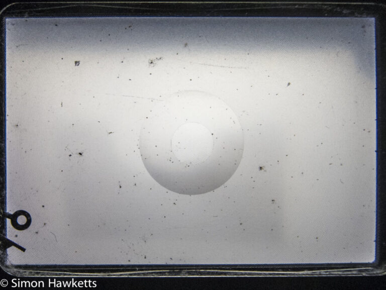
I recently bought a Miranda FV 35 mm SLR camera which has a TTL metered viewfinder fitted. I got the camera quite cheaply, because the viewfinder is marked and dull, but I thought I would look at what, if anything, I could do to get the viewfinder repaired and working again. This post therefore covers the Miranda Fv TTL viewfinder repair.
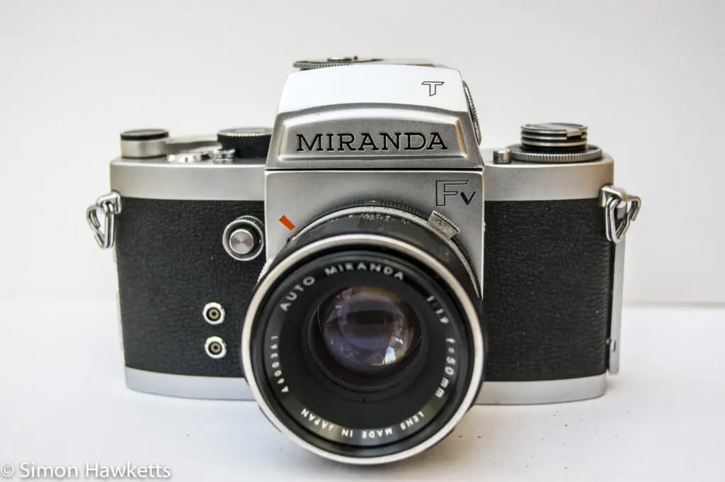
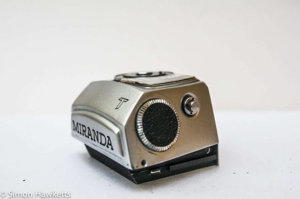
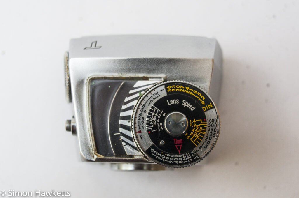
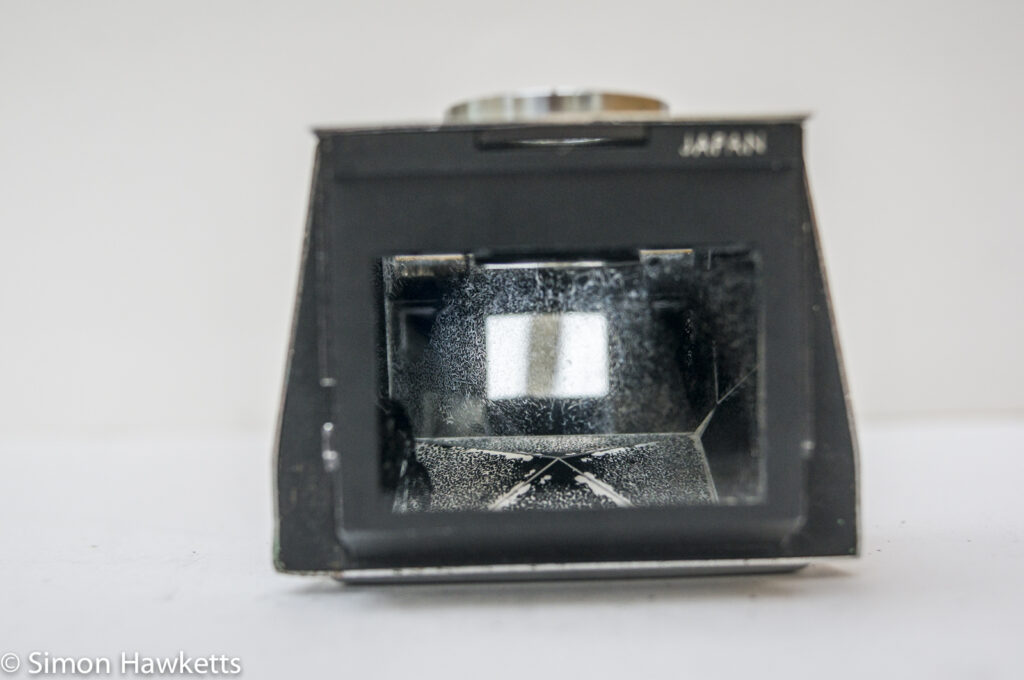
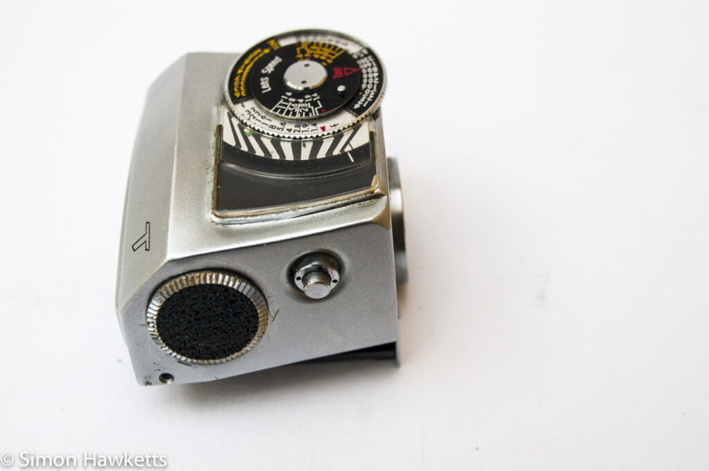
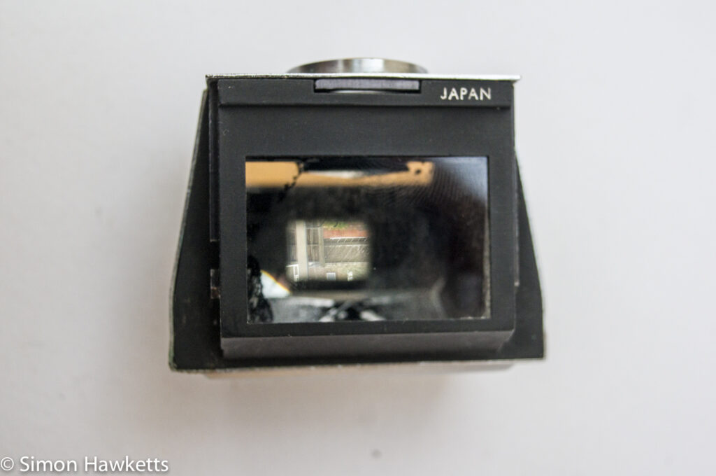
At first, I thought the major problem with the marking in the viewfinder was caused by a leaking battery because the biggest pitted area is just below the battery compartment built into the side of the unit. Actually, I thought that the battery may still be stuck inside the viewfinder because I found it almost impossible to remove the battery cover. However, I tried gripping the side of the cover with my finger nails and suddenly discovered that it would turn, and I could remove it.
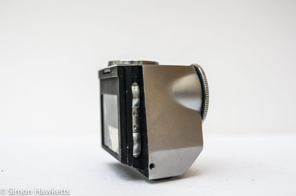
Once the cover was off, I found that there is no battery in place, but the battery contacts are certainly corroded and green. I also discovered, on closer inspection, that there are a couple of tiny screws missing from the side of the prism housing, so I would guess that someone had already tried to get the unit apart and fix it. After a bit of experimentation with the unit on the camera, I found that if I look through the viewfinder and unlock it, so I can move it slightly back, some of the markings in the viewfinder stay in the same place. This suggests that not all the dirt and muck is in the viewfinder component, so I suspect I also need to remove the focusing screen within the camera body and clean it up.
Anyway, back to the TTL viewfinder. To take the unit apart I proceeded to remove the two screws in the black runners which slot into the camera body, and unscrew the round eyepiece, and then I found that I could pull the viewing screen out of the viewfinder housing.
The prism is held in place by two brass pieces which are screwed into the metal housing, one of which also contains a couple of adjustment pots for the light-meter circuit. With these pieces unscrewed, I could get the prism itself out and have a look at it. There is a fair amount of black paint falling off the inner surfaces of the prism, but I think the real problem is with the areas of silvering which are missing.
I have put a couple of bids on some other viewfinders on eBay, so I can get the camera working again. One is a normal viewfinder in working order, the other is a faulty unit with damage to the housing. I’d hoped that I could take the prism out of that damaged unit to fix this TTL one, but now I had the unit apart I could see as I looked at this prism that it is a special type, with small windows next to the viewfinder for the light sensors to sit in. I seem to remember seeing paint which can re-silver mirrors, so may investigate if I can fix the prism instead.
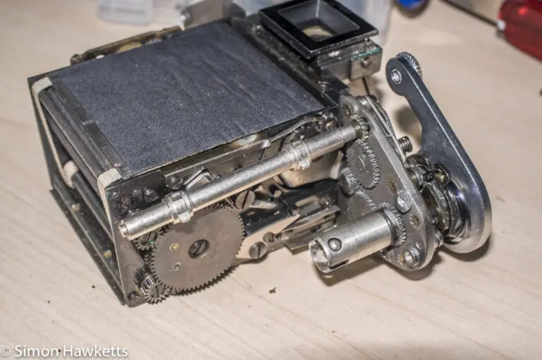
Anyway – I proceeded to remove all the other screws I could find and get as many of the component parts out as I could for cleaning. I removed the bottom assembly, the viewfinder eyepiece lens, the round eyepiece and the metal eyepiece support from the plastic housing with the light sensors in.
Finally, after a lot of difficulty, I got the dial undone at the top of the unit and could remove the actual meter assembly so that the unit casing was free. This along with the other free, non-electrical parts went into an ultrasonic cleaning bath for 3 minutes to get all the muck and dirt off. This clean was actually fairly successful at taking off quite a bit of the green deposit from the battery contacts, but also removed a bit of the paint which makes the word ‘Miranda’ on the front! I’ll need to re-paint that too!
Replacing the battery
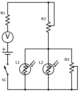
With all the parts exposed I could make an attempt at constructing a circuit diagram of the light-meter which is shown to the left here (circuit drawing made with schemeit).
The idea of drawing out the circuit was that I could change the value of the fixed resister R1 so that the circuit would work with a modern LR44 battery (1.5v) instead of the original mercury cell (1.35v) which is no longer available (or legal).
The value of R1 seems to be about 9.2k when I measure it, although it is marked as 9k. R2 measures about 4k and R3 about 24k. Unfortunately the connection to the light sensitive resistors is broken, but if I measure it they seem to be about 50k at ambient light. Since R3 is set about half way, I would guess that the parallel resistance of the two light sensors and R3 is about 25k (two 50k resisters in parallel).
R2 is also about half way, so I’m going to work on the basis of R2 being a 10k pot, which makes the total resistance in the circuit 25 + 10 + 9.2 = 44.2k. With an original power source of 1.35v, the current flowing would be 1.35 / 44.2 = 0.03 mA or 30uA.
To achieve the same current with 1.5v source I would need a total resistance of 1.5 / 0.03 which is 49k. So if I change R1 for a 14k resistor, I should be able to use an LR44 battery in the unit. Since 14k is not a resistor preferred value, I will need to actually use a 15k.
So, at the moment, that is as far as my repair has got. I’ve removed a lot of the dirt from the casing and can re-wire the unit to work with a modern battery, but the real problem is the prism, which I will either need to repair or replace. I will probably try to find another unit on eBay, ideally a battered one, which I can cannibalise to fix this. That will be the subject of my next post when I hope to have a working unit again.
Discover more from Everything Vintage
Subscribe to get the latest posts sent to your email.


Hi, I am currently trying to fix my Miranda Fv light meter and your article has been very useful. Would you be able to share your further progress on this? I would love to connect and ask some questions to you and I am not that technically savvy but am learning 🙂