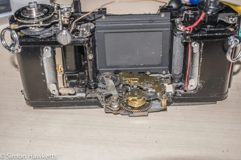
Olympus OM-1n reassembly
In my last post, I described the process I followed to strip my Olympus OM-1n down to clean the shutter and film transport mechanism. In this post, I’m going to describe the Olympus OM-1n reassembly and how I made sure everything was still working.
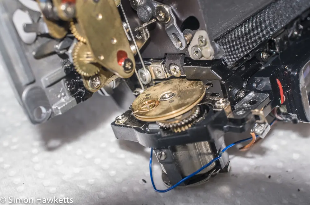
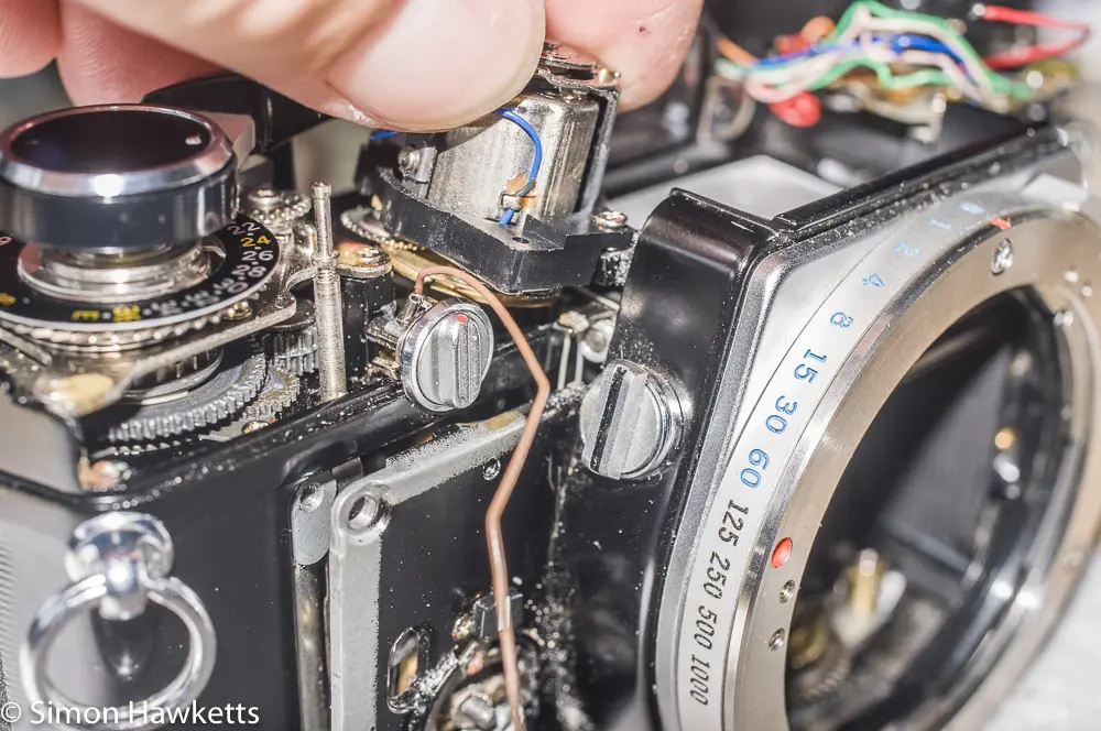
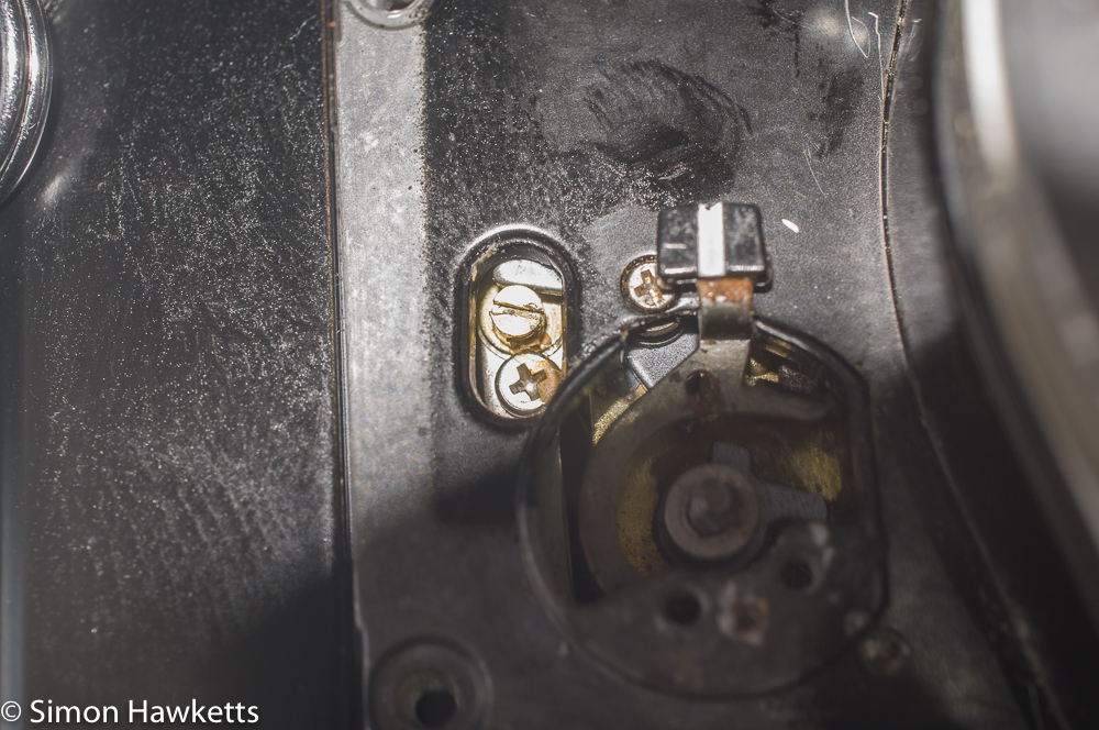
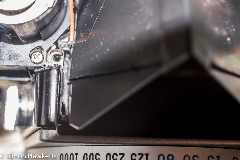
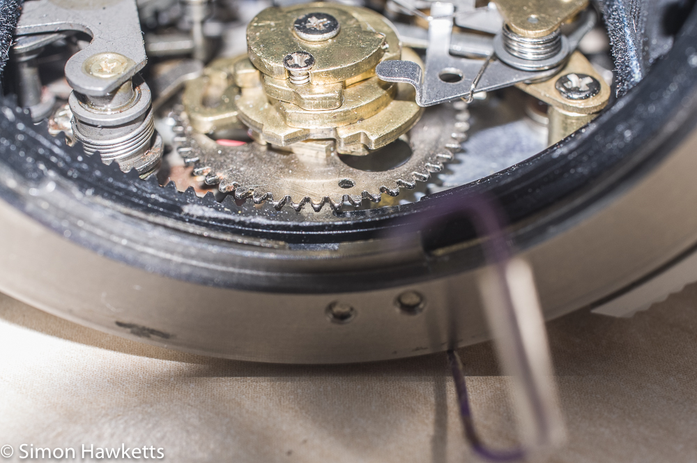
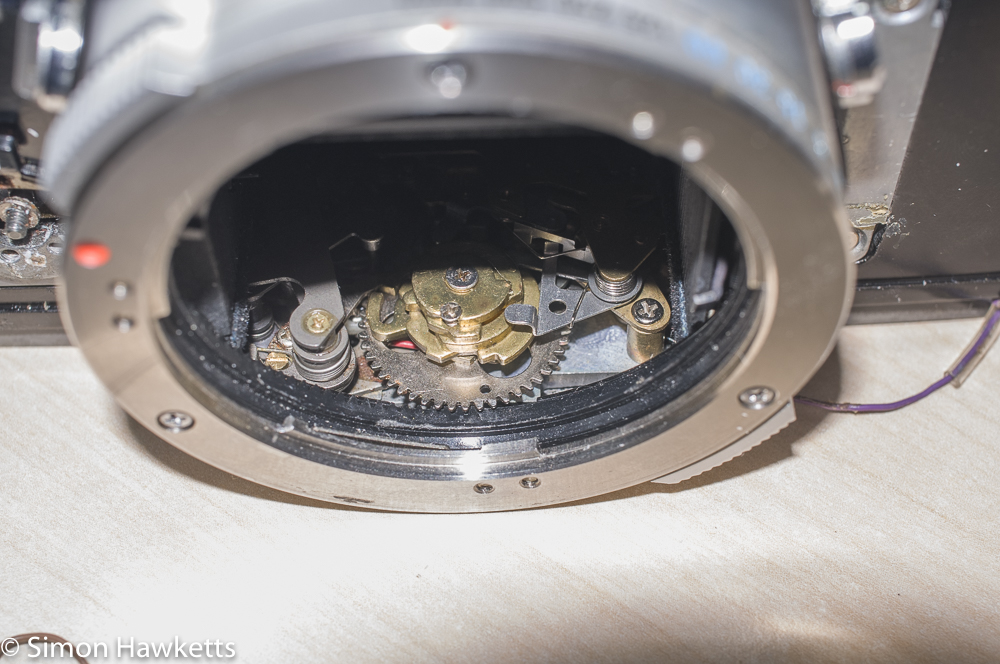
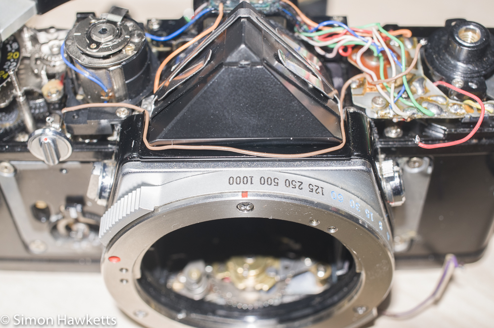
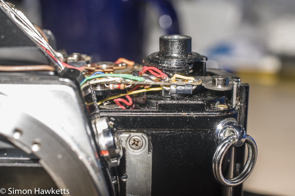
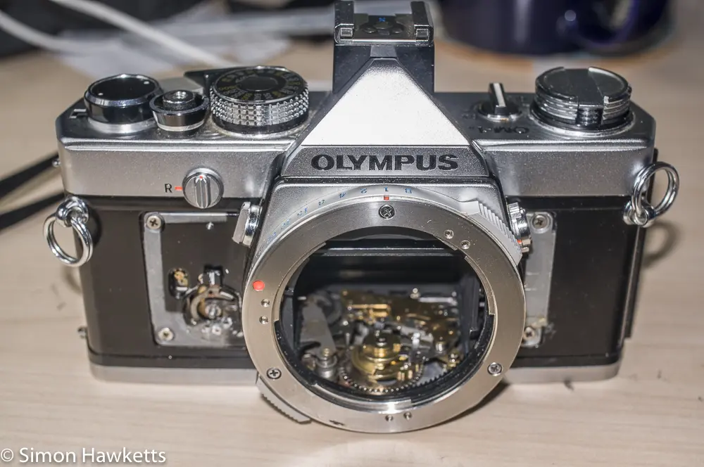
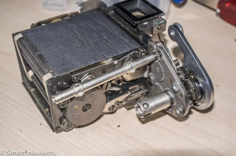
Once I had the shutter mechanism cleaned up, I tried all the speeds to check how accurate they were. At this point I got a bit confused because there seem to be more shutter speed positions on the internal shutter speed wheel than are used by the shutter speed ring fitted to the front of the mirror box. I spend quite some time trying to work out why some of the settings seemed to be a combination of Bulb and slow speeds, i.e. the shutter opens while the release held and then when it is released the escapement runs to time to shutter closed.
Since I couldn’t find a reason for this, I decided to try putting the camera back together and see if it needed to be fully assembled to work. Once I did this, I tried various different shutter speed settings and found that when the shutter dial was set to 1/30th, the actual shutter was operating as if it was set to bulb.
Then it all became clear; what I had worked out was the B setting wasn’t – I had actually gone ‘behind’ B to some additional ‘timed + B’ settings. Once I got the internal speed dial correctly aligned with the front speed dial, everything seemed to work correctly (with one exception – see later). What I found was the 1/1000 setting is marked by a tiny hole in the setting wheel, which is at the front of the camera when 1/1000 is set. Once you know that, it’s easier to align the internal wheel with the shutter speed dial.
Refitting the mirror box to the camera.
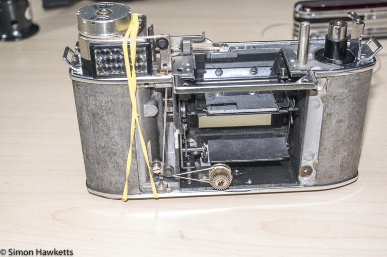
The mirror box, although not difficult to get back into the camera, was a bit tricky because you need to check several things all at once as you fit the assemblies together.
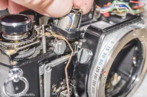
The first thing I did was feed the cord which transfers the lens aperture setting around the drum on the bottom of the galvanometer. That was not too hard, chiefly because I hadn’t removed the cord in its entirety, I’d just removed it from the bottom of the galvanometer. Once it was wrapped round the drum, I found I could refit the galvanometer to the mirror box with loose screws, and then I could refit the mirror box and just lift the galvanometer up to the point I needed to push it into place. I also made sure that moving the aperture follower on the lens mount was transferred to the galvanometer to make sure the cord was in the correct place.
With the exposure meter cord correctly threaded, I then fitted the mirror box back into the camera body. First I tensioned the mirror and then flipped it up using the front most lever on the mirror unit. This placed the flash sync lever in the best position to fit the mirror. Then I fed the purple wire through the hole in the bottom of the camera and refitted the mirror box whilst holding the galvanometer up.
When the box is almost fitted into the camera body, you need to carefully move the exposure meter cord with a pair of tweezers to make sure it doesn’t foul on the camera body. When you have got past that bit and the mirror box is fitted in place, you need to move a lever in the self-timer slot, so the front can be screwed into place.
All this is harder to describe than to actually do – the OM-1 really is one of the easier cameras to work on.
Refitting the prism
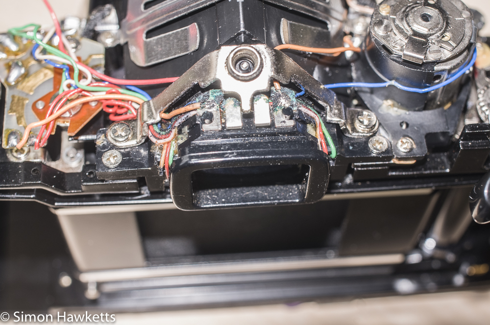
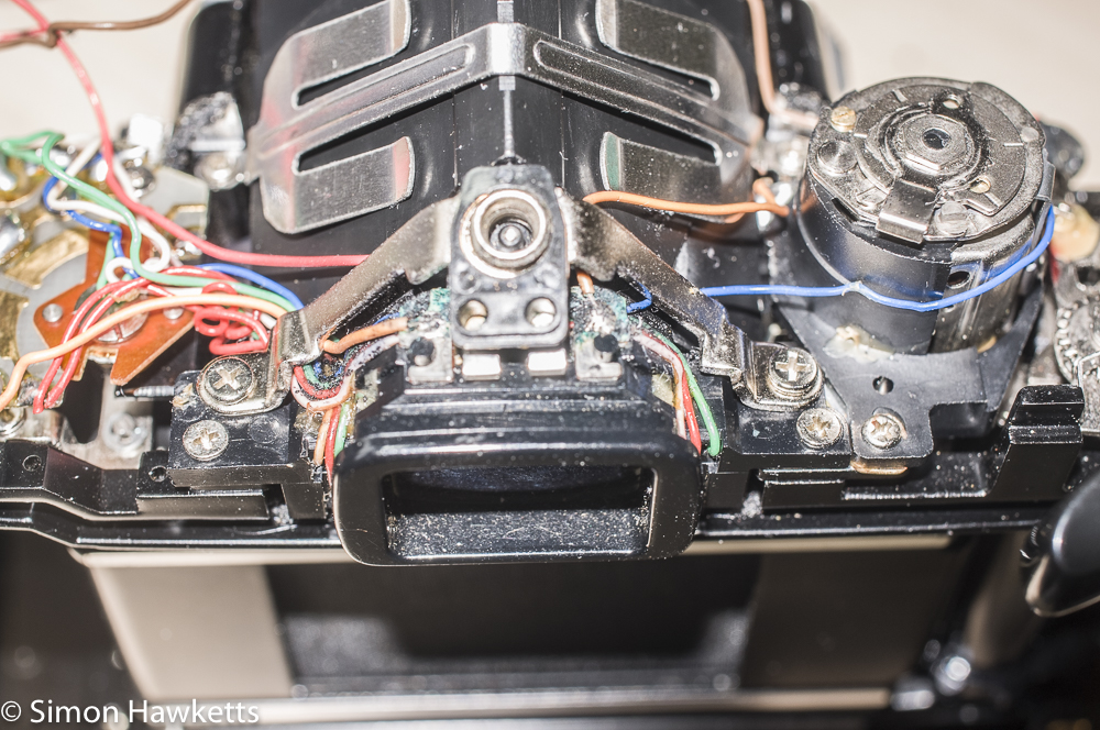
The prism should be easy to re-assemble, and it mostly is apart from the LED, which fits in the side on the mounting next to the galvanometer. This is floating about on an orange wire with a terminal on one side ready to be trapped by the screw which holds the prism harness and I found I had to hold the harness and LED in place with one hand whilst I fitted the screw in the hole with the other hand, holding the screw with a pair of tweezers. I found however that the magnet in the galvanometer was pulling the screw out of place as I tried to force the screw into its hole!
After a lot of messing about, I got it in place and just started the screw with a couple of turns, so I could fit the other one on the other side. Then I finally centred everything up and tightened both screws.
Rest of the re-assembly.
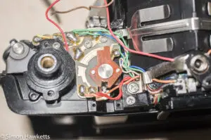
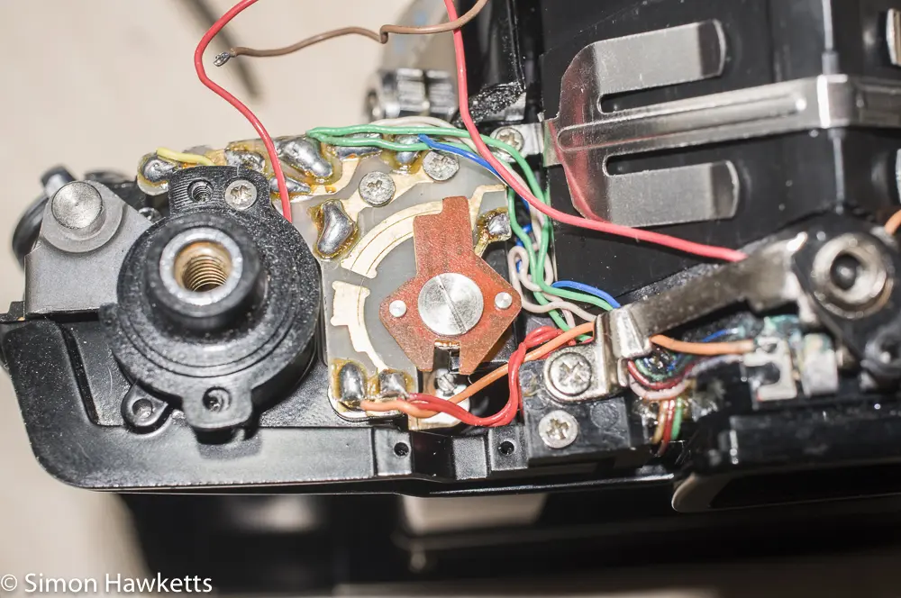
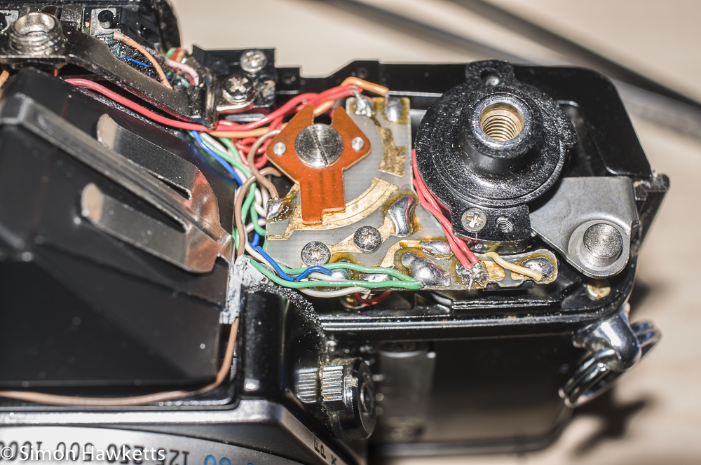
The rest of the reassembly is fairly straight forward. I had to re-solder the four wires which had been disconnected and then feed the wires into places where they wouldn’t do any harm. When you take the camera apart, the wires all seem to bunch up over the top of the on/off switch, so they have to be pushed into the space beside the prism and the circuit board to be out of the way. The two red wires which solder to the front of the circuit board can be pulled into the gap underneath the PCB.
When it comes to fitting the top cover, you need to remember to set the on/off switch to off, set the ISO film speed dial on the cover to 1600 and the corresponding follower on the galvanometer to the same position. Then refit the small plastic piece which sits over the flash sync socket and the spring by the rewind crank. Then you lower the top into place and hope everything slots into place – I have to say on mine it was relatively easy to get them aligned.
With the top on, I first fitted one of the screws in the rewind crank to keep it in place and then temporarily refitted the film advance and made sure the shutter release was working etc. Then I fitted the shutter release properly, screwed on the flash sync ring and added the second screw in the rewind crank position.
At this point I should have fitted the front cover material, the internal light shield over the shutter and the self-timer crank and the camera would be complete again, but I first wanted to run through the basic camera functions to check if everything was working, and it was now that I found a couple of issues.
The first was something which I sort of knew about as I was working on the camera. When I first received it, as well as the shutter being rusted and frozen, the shutter speed dial was also incredibly tight to operate. I didn’t know if this was because the shutter itself was tight, but with it all cleaned out, it was obvious it was the front shutter control rather than the shutter. So I dropped two drops of lighter fluid (Ronsonol) into the control – one at the top and one at the bottom. After I worked the control a few times, it freed up nicely and was easy to turn.
The next issue however was more serious. I said above that when the mirror box was out of the camera, I got confused with the internal shutter speeds. While the camera was apart I thought all the speeds were working, but the Bulb setting had an odd ‘press to open – release to time shut’ problem, but the other speeds were OK but slow. When I got the camera back together and the shutter speed dial calibrated against the internal shutter, I found that all the slow speeds are about right, but for any speed above 1/30th the shutter is travelling without a gap in the curtain. Something is wrong with the timing of the second curtain, so there is no delay between the opening of the first and the opening of the second curtain.
When I was working on the shutter I found a loose spring which seemed to fit on a lever which I’ve subsequently found is probably the disengage lever, but now I wonder if it in fact it should go somewhere else. I found it’s quite difficult to find any pictures of the shutter of an OM-1n on the Internet, so I couldn’t find any hard evidence of where the spring goes, but obviously where I have put it isn’t right. So I’m going to need to strip the camera down again and try to find what the problem is.
That last issue aside, I’m quite pleased that I’ve got so much of the camera working. Considering the state it was in when I received it, it’s pretty good (although obviously not yet working) and I’ve become quite impressed with the OM-1 design.
Discover more from Everything Vintage
Subscribe to get the latest posts sent to your email.

